Troubleshooting Camera Calibration: A Guide for Consistent Behavioral Measurement in Biomedical Research
This guide provides a comprehensive framework for researchers and scientists in drug development to achieve and maintain precise camera calibration, a critical prerequisite for accurate behavioral phenotyping and measurement.
Troubleshooting Camera Calibration: A Guide for Consistent Behavioral Measurement in Biomedical Research
Abstract
This guide provides a comprehensive framework for researchers and scientists in drug development to achieve and maintain precise camera calibration, a critical prerequisite for accurate behavioral phenotyping and measurement. It covers foundational calibration principles, establishes robust methodological procedures, details systematic troubleshooting for common pitfalls, and outlines rigorous validation protocols. By ensuring the geometric accuracy of imaging systems, this resource supports the generation of reliable, reproducible data essential for preclinical and clinical studies.
Why Calibration is Non-Negotiable for Accurate Behavioral Data
Troubleshooting Guides
Guide 1: High Reprojection Error
Problem: The overall reprojection error after calibration is unacceptably high (e.g., ≥ 1 pixel), which can lead to inaccurate measurements in your research data [1] [2].
Solutions:
- Identify and Remove Outlier Images: Use your calibration software's tools to visualize the reprojection error for each image. Exclude images with the highest errors and recalibrate [3] [2].
- Inspect Feature Detection: Manually check calibration images for false or inaccurate detections of pattern features (like checkerboard corners). Remove or retake images where detection has failed [3].
- Increase Data Variety: Ensure your image set includes the pattern at various angles, distances, and positions, covering the entire field of view, especially the edges. Avoid overfitting by using non-repetitive perspectives [3] [1].
- Use a More Complex Distortion Model: For wide-angle or fisheye lenses, try calibrating with a higher-order distortion model (e.g., 3 radial distortion coefficients instead of 2) or a specialized fisheye model [3] [4].
- Verify Pattern Flatness and Rigidity: Ensure your calibration target is mounted on a perfectly flat, rigid surface to prevent deformations that introduce errors [1] [4].
Guide 2: Calibration Failure or Non-Convergence
Problem: The calibration algorithm fails to compute camera parameters or returns a "linear calibration failed" error [4].
Solutions:
- Check Pattern Parameters: Verify that the correct number of inner corners (rows and columns) and the exact physical measurement of the squares/dots are provided to the software. For checkerboards, count black-to-black inner corners [3] [5] [4].
- Ensure Sufficient Pattern Tilt: Capture many images with the pattern tilted at significant angles (up to ±45° or ±60° relative to the camera plane). Avoid having all images be fronto-parallel [3] [1] [4].
- Improve Pattern Visibility: Confirm the entire calibration pattern is visible in all images used and is not partially blocked or at an overly acute angle to the camera [5] [4].
- Review Image Quality: Avoid motion blur, uneven lighting, glare, or reflections on the pattern. Use diffuse, controlled lighting and a stable setup [3] [4].
- Use More Images: Capture a larger set of images (e.g., 20-50) to give the algorithm sufficient data to converge on a solution [3] [1].
Guide 3: Inaccurate 3D Measurements After Calibration
Problem: Even with a low reprojection error, the 3D world measurements derived from the calibrated camera are inaccurate.
Solutions:
- Validate with Extrinsics Visualization: Use the software's feature to plot the locations of the camera and the calibration pattern. Look for impossible geometries, such as the pattern appearing behind the camera [3] [2].
- Check Calibration Coverage: Visually confirm that your calibration images provide even coverage of the camera's entire field of view. If there are noticeable gaps, capture additional images to fill them [3] [1].
- Re-calibrate at Application Resolution and Focus: The camera must be calibrated at the exact resolution and focus settings used during data collection. Any change in zoom or focus invalidates the calibration [3] [1].
- Verify Ground Plane Alignment: For motion capture systems, ensure the calibration board was perpendicular to the floor during the calibration process, as an incorrect ground plane can skew kinematics [5].
Frequently Asked Questions (FAQs)
Q1: What is an acceptable reprojection error for behavior measurement research? A: A reprojection error of less than 0.5 pixels is generally considered good for precise measurement applications. A value greater than 1 pixel is often unacceptable and indicates a need for recalibration [1] [2]. However, a low error is necessary but not sufficient; always validate your results visually and through other metrics [1].
Q2: How many calibration images do I need, and how should I capture them? A: While 10-20 images are a common starting point, using around 50 different images is a robust rule of thumb for high-precision research [3] [1]. Capture these by moving the pattern throughout the intended "calibration volume"—at different 3D orientations, distances, and angles—ensuring coverage of the entire field of view, especially the edges and corners [3] [1] [2].
Q3: My camera has auto-focus. Can I use it during calibration? A: No. You must disable auto-focus and auto-exposure. These automatic settings change the camera's intrinsic parameters (like focal length) during the capture process, which invalidates the consistency required for a stable calibration. Use fixed, manual settings for focus, exposure, and zoom [3] [1].
Q4: Why does my stereo or multi-camera system have poor 3D tracking accuracy? A: This can stem from several calibration-related issues:
- Poor Camera Synchronization: Ensure all cameras are hardware-synchronized or use a post-hoc synchronization method (e.g., a distinct motion like a hand punch) [5].
- Insufficient Overlapping Field of View: Reposition cameras so that the subject is visible by at least two cameras at all times to avoid occlusions [5].
- High Lens Distortion at the Edges: Wide-angle lenses may have significant distortion at the image edges. Ensure your calibration images cover these areas to model the distortion correctly [3] [6].
Q5: What are the best practices for creating or selecting a calibration target? A: The quality of the target is critical [1].
- Material: It should be printed on a flat, rigid, and non-reflective material. Avoid flimsy paper [3] [1].
- Accuracy: Use a professional printing service to ensure the pattern's geometry (e.g., square size) is accurate and without scaling [3] [1].
- Size and Coverage: The pattern should be large enough to cover a significant portion of the image (ideally 80% of the frame when parallel to the camera) [3].
- Border: Include a white border around the pattern to make it easier for the software to detect [3].
Calibration Error Metrics and Standards
The table below summarizes key quantitative metrics used to evaluate calibration accuracy, helping you determine if your system meets the required standards for measurement validity.
| Metric | Description | Acceptable Threshold for Precision Research |
|---|---|---|
| Mean Reprojection Error [3] [1] [2] | The root-mean-square (RMS) distance (in pixels) between detected pattern points and their projected locations using the calibrated model. | < 0.5 pixels (Good) [3] [1] |
| Standard Error of Parameters [2] | The standard error (uncertainty) for each estimated parameter (e.g., focal length, distortion coefficients). | A 95% confidence interval is within ±1.96σ of the estimated value. The smaller, the better [2]. |
| Pattern Distance [5] | The physical distance between the calibration target and the cameras during image capture. | Should be close to the working distance. For some systems, keep it < 5 meters for reliable detection [5]. |
Experimental Protocol: Achieving a High-Accuracy Calibration
This detailed methodology ensures reliable and repeatable camera calibration for scientific measurement.
Pre-calibration Setup
- Camera Locking: Mechanically secure the camera on a stable tripod or mount. Disable auto-focus, auto-exposure, and image stabilization. Set the resolution to the value that will be used in your experiments and do not change it [3] [1].
- Target Preparation: Obtain a high-quality calibration target (e.g., a checkerboard) printed on a rigid, flat, non-reflective surface by a professional print shop. Precisely measure the size of one square using calipers and note the number of inner corners (rows x columns) [3] [1].
- Lighting Control: Set up diffuse, even lighting to minimize shadows, glare, and reflections on the target [3] [4].
Image Acquisition
- Capture Volume: Move the target throughout the entire calibration volume—a cone-shaped space from the camera's sensor. Capture images at different distances, and tilt the pattern up to ±45 degrees to introduce foreshortening [3] [1].
- Frame Coverage: Ensure the pattern appears in all areas of the frame, including the four corners and edges. Capture at least one image where the pattern fills the entire frame [3] [1].
- Image Set: Capture a minimum of 20-50 images from diverse and non-repetitive viewpoints. Save images in a lossless format (e.g., PNG) [3] [1].
Software Calibration and Validation
- Parameter Input: Load the images into your calibration software (e.g., OpenCV, MATLAB). Input the correct physical square size and the number of inner corners [3] [2].
- Model Selection: For standard lenses, start with a model that includes 2 radial distortion coefficients. For wide-angle or fisheye lenses, use a specialized model with more coefficients [3] [4].
- Error Analysis: After calibration, inspect the mean reprojection error. If it is high (>0.5 px), use the software's tools to visualize errors per image and remove outliers. Recalibrate [3] [2].
- Extrinsics Check: Plot the estimated positions of the camera and the pattern to identify impossible geometries, which indicate a flawed calibration [3] [2].
The Scientist's Toolkit: Essential Research Reagents and Materials
| Item | Function / Explanation |
|---|---|
| High-Quality Calibration Target [3] [1] | A geometrically precise pattern (e.g., checkerboard or dot grid) on a rigid, flat substrate. It provides known physical reference points for the calibration algorithm. |
| Precision Measuring Tool [3] | Calipers or a micrometer to accurately measure the physical dimensions of the pattern's features, which is crucial for converting pixel measurements to real-world units. |
| Stable Camera Mount [3] [1] | A heavy-duty tripod or rig to prevent camera shake and blur, ensuring sharp images and a consistent camera position during calibration and data collection. |
| Controlled Lighting Source [3] [4] | Diffuse lights (e.g., softboxes) that provide even illumination, minimizing shadows, glare, and reflections that can corrupt feature detection on the target. |
| Calibration & Analysis Software [3] [2] | Computer vision tools (e.g., OpenCV, MATLAB Computer Vision Toolbox) that implement algorithms to detect the pattern and calculate camera parameters and errors. |
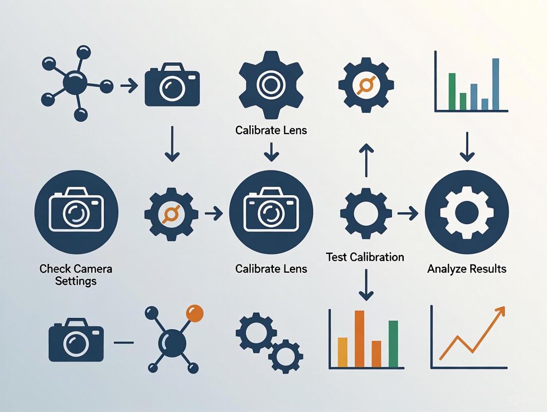
Camera Calibration and Validation Workflow
The diagram below outlines the critical steps for a reliable camera calibration process and key validation checkpoints to ensure measurement validity.
FAQs on Lens Distortion and Calibration
Q1: What are the main types of lens distortion and how do they affect my tracking data? Lens distortion is an optical aberration that causes straight lines in the real world to appear curved in an image. The primary types you will encounter are barrel distortion and pincushion distortion [7] [8] [9]. A third, more complex type is mustache distortion, which is a hybrid of the first two [7] [9].
- Barrel Distortion: This causes straight lines to bulge outward from the center of the image, creating a "barrel" effect. It is common with wide-angle lenses [7] [8].
- Pincushion Distortion: This causes straight lines to bend inward, creating a pinched effect toward the center. It is often seen in telephoto or zoom lenses [7] [9].
- Mustache Distortion: This is a combination of both barrel and pincushion distortion, where the image curves outward near the centre and inward toward the edges, creating a wavy warping [7] [9].
In animal tracking, these distortions introduce spatial inaccuracies. The position of an animal's joint, for example, will be measured incorrectly in the image, especially if it is near the edge of the frame. This can lead to significant errors in calculating gait, distance traveled, or posture [3] [7].
Q2: Why is camera calibration crucial for consistent behavior measurement? Camera calibration is the foundational first step for any quantitative image analysis [3]. A calibrated camera allows you to correct for lens distortion and obtain precise measurements of objects in the real world from your 2D images [3]. Without it, the inherent distortions of your lens will cause your data to be systematically biased, compromising the validity and repeatability of your research. For multi-camera setups used for 3D reconstruction, calibration is even more critical to ensure all cameras are working from a single, accurate geometric model [10].
Q3: What is a reprojection error and what is an acceptable value? The reprojection error is the difference between where a known point in the real world (from your calibration pattern) is detected in your image and where the camera's mathematical model "projects" it should appear. It is the primary metric for assessing the quality of your calibration [3]. This error is measured in pixels. Ideally, the mean reprojection error should be less than 0.5 pixels for a reliable calibration [3].
Q4: My calibration has a high reprojection error. What should I do? A high error indicates a problem with your calibration image set or setup. You can:
- Identify and remove outliers: Use your calibration software (e.g., MATLAB) to visualize the errors per image and exclude the images with the highest errors before recalibrating [3].
- Inspect feature detection: Manually check all calibration images to ensure the software correctly identified all the pattern features (like corners) without any false detections [3].
- Improve your image set: Ensure you have a sufficient number of images (10-20) with a wide variety of angles, distances, and coverage of the field of view. Avoid overfitting by using similar perspectives [3].
Troubleshooting Guides
Guide 1: Solving Common Camera Calibration Failures
| Problem Area | Specific Issue | Recommended Solution |
|---|---|---|
| Calibration Target | Charuco board not detected [10]. | Use a large, rigid, flat board. Ensure lighting is even and minimizes glare. Use the exact, predefined board layout required by your software [3] [10]. |
| Pattern only covers the center of the frame [3]. | The pattern should cover at least 50%, ideally 80%, of the image when parallel to the camera. Capture images where the pattern is close to all edges and corners [3]. | |
| Image Set | "Not enough values to unpack" or similar error [10]. | This means cameras lack shared views. Ensure each camera sees the board simultaneously with at least one other camera. Check for mirrored images from front-facing phone cameras and disable this feature [10]. |
| High reprojection error due to overfitting [3]. | Capture a diverse set of images: fronto-parallel, tilted up to ±45 degrees, and with the target near all edges. Avoid taking all images from the same distance and angle [3]. | |
| Camera Setup | Changing focus or zoom after calibration [3]. | Use fixed focus and a fixed zoom setting. Do not change these settings during or after the calibration process, as they alter the lens's intrinsic properties [3]. |
| Auto-exposure causing varying image brightness [3]. | Use a fixed exposure setting to ensure consistent images. Have controlled, diffuse lighting to minimize shadows and glare [3] [10]. |
Guide 2: Choosing and Using a Calibration Target
The calibration target is a physical object with a known geometry. The software uses it to model your camera's distortion. Here are the key specifications and choices:
Table: Calibration Target Specifications
| Feature | Requirement | Why It Matters |
|---|---|---|
| Flatness | Must be perfectly flat and rigid [10]. | A warped target will introduce errors in the 3D-to-2D mapping. Mount printed patterns on stiff cardboard or poster board [10]. |
| Print Quality | High contrast; no scaling applied during printing [3]. | Ensures the software can detect the pattern's features accurately. Use high-quality vector formats (PDF, SVG) where possible [3]. |
| Material | Non-reflective, matte surface [3]. | Prevents glare and hotspots from obscuring the pattern, which would lead to failed feature detection [3] [10]. |
| Pattern Size | Cover 50-80% of the image at working distance [3]. | A larger board is easier for cameras to detect. For small boards, hold them closer, but ensure they remain visible to multiple cameras simultaneously [10]. |
Table: Common Types of Calibration Patterns
| Pattern Type | Description | Best For |
|---|---|---|
| Checkerboard | A grid of alternating black and white squares [7]. | A common, versatile pattern suitable for most camera calibration tasks in computer vision [7]. |
| Charuco Board | A grid of black and white squares with unique ArUco markers in each alternate square [10]. | Enhanced pose estimation and robustness against occlusion. Recommended for tools like FreeMoCap [10]. |
| Dot Pattern | A grid of circles or dots [9]. | Used in specific standardized measurements (CPIQ compliance) [9]. |
Experimental Protocols
Protocol 1: Reliable Multi-Camera Calibration for 3D Tracking
This protocol details the steps for calibrating a multi-camera system, such as those used in motion capture setups like FreeMoCap, to ensure accurate 3D reconstruction of animal movement [10].
Methodology:
- Preparation:
- Recording:
- Slowly move and tilt the calibration board through the shared volume where the animal will be tracked. Show the board to each pair of cameras for 5-10 seconds to ensure you capture at least 200 shared frames per pair [10].
- Capture the board in many orientations: fronto-parallel to the camera, tilted up to ±45 degrees, and positioned so its edges are close to the sides of the frame [3].
- Ensure the board is well-lit and free of glare throughout the recording [10].
- Processing:
- Load the recorded videos or images into your calibration software (e.g., FreeMoCap, OpenCV, MATLAB).
- Input the physical dimensions of the pattern squares accurately [3].
- Run the calibration algorithm to compute the intrinsic parameters (for each camera) and extrinsic parameters (the positions of cameras relative to each other).
- Validation:
The workflow for this multi-camera calibration process is summarized in the following diagram:
Protocol 2: Quantifying Lens Distortion with a Checkerboard
This protocol uses a standard checkerboard to measure the specific distortion coefficients of a lens, which can be used to correct images for precise 2D analysis [3] [9].
Methodology:
- Image Acquisition:
- Place the checkerboard in the camera's field of view.
- Capture a set of 10-20 images with the pattern at different orientations (parallel, tilted) and positions (center, edges, corners). The pattern should cover most of the frame in several images [3].
- Use uncompressed (e.g., PNG) and unmodified images for calibration [3].
- Software Analysis:
- Model Fitting:
- The software fits a distortion model to the data. A common starting point is the radial distortion model, expressed as:
r_u = r_d + k1 * r_d^3 + k2 * r_d^5[9] wherer_dis the distorted radius,r_uis the undistorted radius, andk1,k2are the distortion coefficients [9]. - For complex "mustache" distortion, higher-order models (5th or 7th order polynomials) may be required [9].
- The software fits a distortion model to the data. A common starting point is the radial distortion model, expressed as:
- Correction:
- The calculated coefficients are used to create a correction map (e.g., an STMap in VFX) that can transform distorted images into undistorted ones, or vice-versa [7].
The Scientist's Toolkit
Table: Essential Research Reagent Solutions for Camera Calibration
| Item | Function | Technical Notes |
|---|---|---|
| Charuco Board | Provides a known geometric pattern for high-accuracy calibration and robust pose estimation [10]. | Use the exact definition required by your software. Must be printed at high contrast and mounted rigidly [10]. |
| Checkerboard Chart | A standard pattern for estimating camera parameters and distortion coefficients [7] [9]. | Ensure known physical dimensions of squares are input into the software. Vector formats (PDF/SVG) prevent scaling errors [3]. |
| Software: OpenCV | Open-source library with comprehensive functions for camera calibration, corner detection, and image correction [3]. | Uses the pinhole camera model. Can estimate intrinsic parameters, distortion coefficients, and reprojection error [3]. |
| Software: Imatest | Commercial solution providing detailed analysis of distortion, modulation transfer function (MTF), and other image quality factors [9]. | Offers multiple distortion models (3rd order, 5th order, tangent) and is highly accurate with checkerboard patterns [9]. |
| Software: MATLAB | Computing environment with a Computer Vision Toolbox for calibration and visualization of errors and extrinsic parameters [3]. | Useful for identifying and removing outlier images that contribute to high reprojection errors [3]. |
The logical process of troubleshooting a failed calibration, from symptom to solution, is visualized below:
Your Troubleshooting Guide to Camera Calibration
This guide provides clear answers to common challenges in camera calibration for behavior measurement research, helping you ensure the geometric accuracy essential for your data.
Frequently Asked Questions
Q1: What are intrinsic and extrinsic parameters, and why do I need both for 3D measurements?
- A: Intrinsic parameters describe the internal, optical properties of the camera itself, such as its focal length and lens distortion. Extrinsic parameters describe the camera's position and orientation in the 3D world. You need both to accurately relate the 2D coordinates of a point in your image to its actual 3D location in your research environment [11] [12]. The intrinsic parameters project the 3D world onto the 2D sensor, while the extrinsics define the camera's viewpoint.
Q2: My calibration reprojection error is high. What are the most common causes?
- A: A high reprojection error indicates that the calibrated model does not accurately predict where known 3D points will appear in your 2D images. The most common causes are:
- Poor Quality Images: Blurry images, poor lighting, or calibration patterns that are not in full focus.
- Insufficient View Variety: Not capturing the calibration pattern from a wide enough range of angles and positions relative to the camera. A minimum of 10-15 images from different viewpoints is often recommended [12].
- Inaccurate Feature Detection: The algorithm incorrectly identifying the key points (like chessboard corners) in your images. Always visually verify that the corners are detected correctly [12].
- Inadequate Pattern Coverage: The calibration pattern does not fill the entire field of view, especially the edges where lens distortion is most pronounced.
Q3: How can I check if my lens distortion correction is working properly?
- A: After applying your distortion coefficients, capture an image of a scene with many straight lines, like a building or a dedicated grid pattern. If the correction is successful, lines that are straight in the real world should appear straight in your corrected image, with no visible curving, especially at the edges [12].
Q4: What is the difference between calibration and profiling, and do I need both?
- A: In the context of camera calibration for geometric measurement:
- Calibration is the process of determining your camera's intrinsic and extrinsic parameters to correct geometric distortions [11] [12].
- Profiling (more common in color science) characterizes the color reproduction of a monitor or camera to ensure accurate color representation [13]. For consistent 3D behavior measurement, geometric calibration is the essential first step. Profiling is crucial for photometric accuracy but is a separate process.
Core Parameter Reference Tables
Table 1: Intrinsic Camera Parameters
These parameters are internal to the camera and define how it projects the 3D world onto a 2D image sensor [11].
| Parameter | Description | Mathematical Representation | Role in Imaging |
|---|---|---|---|
Focal Length (f_x, f_y) |
Distance between the lens and image sensor, determining the field of view. | Pixels (e.g., f_x = F/p_x) |
Controls magnification and perspective. |
Principal Point (c_x, c_y) |
The optical center of the image, where the optical axis intersects the sensor. | Pixels | Defines the image center for the projection. |
Radial Distortion (k_1, k_2, k_3) |
Corrects for light rays bending more at the lens edges than center ("barrel" or "pincushion" distortion) [11]. | x_distorted = x(1 + k_1*r^2 + k_2*r^4 + k_3*r^6) |
Makes straight lines appear straight in the image. |
Tangential Distortion (p_1, p_2) |
Corrects for distortion when the lens and image sensor are not perfectly parallel [11]. | x_distorted = x + [2*p_1*x*y + p_2*(r^2+2*x^2)] |
Corrects for decentering of the lens elements. |
Table 2: Extrinsic Camera Parameters
These parameters describe the camera's position and orientation in the 3D world [11].
| Parameter | Description | Mathematical Representation | Role in 3D Reconstruction |
|---|---|---|---|
| Rotation | The 3D orientation of the camera relative to the world coordinate system. | 3x3 Matrix (R) or Rotation Vector | Determines the viewing direction of the camera. |
| Translation | The 3D position of the camera relative to the world coordinate system origin. | 3x1 Vector (t) | Locates the camera in space. |
The Scientist's Toolkit: Essential Research Reagents & Materials
Table 3: Essential Materials for Camera Calibration
| Item | Function in Experiment |
|---|---|
| Checkerboard or ChArUco Board | A known geometric pattern with high-contrast features (e.g., squares) used as a calibration target. Its well-defined 3D geometry provides the reference points for calculating camera parameters [12]. |
| OpenCV Library | An open-source computer vision library that provides robust, ready-to-use functions for corner detection, parameter calculation, and image correction, streamlining the calibration workflow [12]. |
| Rigid Flat Surface | A stable, non-flexible platform (e.g., an acrylic sheet) to mount the calibration target. This ensures the known geometry of the pattern remains consistent during data collection. |
| Controlled Lighting Setup | Consistent and even illumination is critical for reducing noise and ensuring the calibration pattern features are detected accurately and consistently across all images. |
| Active Target (High-Precision) | A high-resolution flat screen that displays a sequence of coded patterns. It can generate dense, high-accuracy 3D-2D correspondences, often outperforming static patterns [14]. |
Experimental Protocols for Reliable Calibration
Detailed Methodology: Checkerboard Calibration with OpenCV
This is a standard protocol for calibrating a single camera using a checkerboard pattern [12].
- Prepare Calibration Target: Print a checkerboard pattern on a rigid, flat surface. Note the number of inner corners (e.g., 9x6) and the real-world size of each square.
- Capture Calibration Images:
- Use the camera to take at least 15-20 images of the pattern.
- Vary the pattern's position and orientation significantly: move it left/right, up/down, tilt it forward/backward, and rotate it.
- Ensure the pattern is in focus and the entire image is well-lit without glare or shadows.
- Ensure the pattern appears in different parts of the image, especially near the edges and corners, to characterize distortion across the entire field of view.
- Detect Corner Points: For each image, use an algorithm (like
cv2.findChessboardCornersin OpenCV) to automatically detect the 2D pixel coordinates of the inner corners of the checkerboard. - Define Object Points: For each image, define the 3D world coordinates of the checkerboard corners. Assume the board is flat on the XY-plane (Z=0). The coordinates are typically defined based on the square size (e.g., 2 cm).
- Calibrate the Camera: Pass the collected 2D image points and 3D object points to a calibration function (like
cv2.calibrateCamera). This function uses an optimization algorithm to find the intrinsic parameters (camera matrix and distortion coefficients) and extrinsic parameters (rotation and translation vectors for each image) that best map the 3D points to the 2D pixels [12]. - Validate Results: Calculate the reprojection error. This is the average distance in pixels between the detected corner points in your images and the points projected back into the image using the calibrated camera parameters. A lower error (typically < 0.5 pixels) indicates a better calibration.
Workflow and Relationship Diagrams
Camera Calibration Workflow
Intrinsic vs Extrinsic Parameters
FAQs: Camera Calibration in Behavior Measurement Research
Q1: What are the concrete signs that my camera system is poorly calibrated? A poorly calibrated camera system exhibits clear physical and data-level symptoms. Physically, straight lines in your capture volume appear curved (barrel or pincushion distortion), and objects seem stretched or misaligned [15]. In your data, you may observe inconsistent tracking of subjects across different camera views, inaccurate depth estimation for 3D reconstruction, and a high reprojection error (typically above 0.5 pixels) when you validate your calibration [3] [16]. These inaccuracies directly compromise the validity of kinematic or behavioral measurements.
Q2: How does poor calibration lead to compromised study outcomes? The primary consequence is the introduction of systematic measurement error. This drift means that the spatial data you collect—such as distance traveled, velocity, or posture angles—does not accurately reflect the subject's true behavior [15]. For example, in a rodent open field test, poor calibration could cause an overestimation of travel distance, falsely indicating higher activity levels. In pharmaceutical development, such data flaws threaten the reliability of efficacy and safety assessments, leading to incorrect conclusions and potentially jeopardizing regulatory compliance [17] [18].
Q3: Our multi-camera calibration keeps failing. What are we doing wrong? Failed multi-camera calibration is often due to insufficient shared views. Every camera in your system must see the calibration pattern at the same time as at least one other camera to establish a common 3D reference [10] [5]. Other common pitfalls include:
- Non-rigid calibration target: A bent or flexible board makes feature detection unreliable [10].
- Inadequate pattern coverage: The pattern should cover a significant portion of the image (ideally 80%) from multiple angles and distances [3].
- Glare and poor lighting: Glare can obscure the pattern, while low contrast prevents the software from detecting key points [10] [5].
Q4: How often should we recalibrate our camera system? The need for recalibration is triggered by any change to your setup or evidence of measurement drift. Recalibrate if you change the camera's focus, zoom, or resolution [3], physically bump or move a camera, or observe a sudden shift in your control data. As a best practice, even for a stable setup, perform a validation check before a critical experiment series to detect and correct for subtle drift.
Troubleshooting Guide: Solving Common Calibration Problems
| Problem | Symptom | Likely Cause | Solution |
|---|---|---|---|
| High Reprojection Error | High mean error (>0.5 px) during/after calibration [3]. | Poor quality image set, incorrect pattern definition, or moving calibration target [3]. | Capture new images with stable camera; ensure target is rigid [3] [10]. |
| Failed Calibration | Software error (e.g., "not enough values to unpack") [10]. | Lack of shared pattern views between cameras or mirrored video feed [10]. | Reposition cameras/target; disable phone camera mirroring [10]. |
| Distorted 3D Reconstructions | Subject's shape appears warped; inconsistent limb lengths [5]. | Incorrect lens distortion coefficients or poor coverage of calibration images [15] [3]. | Capture calibration images across entire field of view, especially edges [3]. |
| Inaccurate Depth Measurement | Systematic error in distance/position measurements along the Z-axis [15]. | Miscalibrated translation matrix (extrinsic parameter) or camera angles too narrow [15] [5]. | Recalibrate with target at different depths; reposition cameras for better angular separation (40-90°) [5]. |
Calibration Validation Metrics and Benchmarks
For reliable research, quantitative validation is non-negotiable. The table below outlines key metrics to assess your calibration quality.
| Metric | Target Value | Description & Impact on Data |
|---|---|---|
| Mean Reprojection Error [3] [16] | < 0.5 pixels | Average difference between detected and projected points. Higher values indicate poor parameter estimation and general measurement inaccuracy. |
| Parameter Standard Deviation | < 1-2% of mean value | Variation in estimated parameters (e.g., focal length) across calibration runs. High deviation indicates an unstable or noisy calibration. |
| Distortion Coefficient Stability | Low fluctuation | Consistency of k1, k2 (radial) and p1, p2 (tangential) coefficients. Instability suggests insufficient image coverage or pattern detection issues. |
Experimental Protocol: Validating Calibration for a Longitudinal Study
Objective: To verify that camera calibration remains stable over the duration of a multi-week study, ensuring no significant measurement drift has occurred.
Materials: The original calibration target (e.g., Charuco board), a fixed validation fixture with known dimensions placed within the capture volume.
Methodology:
- Pre-Study Calibration: Perform a full, multi-view camera calibration following best practices [3]. Save the calibration parameters (intrinsics, extrinsics, distortion coefficients).
- Validation Fixture Scan: Record a 30-second session of the fixed validation fixture placed in a standard orientation within the volume.
- Weekly Check: Before each week's data collection, repeat step 2 without performing a new calibration.
- Data Analysis:
- Reconstruct the 3D position of the fixture's key points using the original calibration parameters.
- Calculate the root mean square (RMS) error between the reconstructed fixture dimensions and its known, physical dimensions.
- Track this RMS error over time. A significant upward trend indicates measurement drift.
Interpretation: A stable, low RMS error confirms calibration integrity. A rising error necessitates investigation and likely recalibration to maintain data validity.
| Item | Function & Importance | Specification Notes |
|---|---|---|
| Calibration Target | Provides known geometry for estimating camera parameters. Planar targets (checkerboard/Charuco) are most common [3] [16]. | Must be flat and rigid [10]. Square size must be known and consistent. High-contrast, non-reflective surface is critical [3]. |
| Software Library (OpenCV) | Industry-standard library for computer vision. Contains full implementations for target detection, parameter calculation, and undistortion [3]. | Use functions like findChessboardCorners, calibrateCamera, and undistort. |
| Validation Fixture | An object of known, stable dimensions used to check calibration accuracy independently of the original target. | Should be different from the calibration target to avoid bias. Ideal for detecting measurement drift over time. |
| Reprojection Error Script | A custom script to calculate the mean reprojection error, providing a key quantitative metric of calibration quality [16]. | The core calculation involves the Euclidean distance between observed image points and points projected using the calibrated parameters [16]. |
Workflow and Impact Diagrams
The following diagram illustrates the logical chain of how poor calibration leads to compromised research outcomes.
Logical Chain from Poor Calibration to Compromised Outcomes
The diagram below outlines a robust calibration and validation workflow to prevent the issues detailed above.
Camera Calibration and Validation Workflow
Building Your Calibration Protocol: From Checkerboards to Fisheye Lenses
In scientific research, particularly in fields requiring consistent behavior measurement such as drug development, the accuracy of your camera system is paramount. This accuracy is established through a process called camera calibration, which corrects for lens distortion and sensor imperfections to ensure that measurements made from images are reliable and metrologically valid. The choice of calibration target is the first and one of the most critical steps in this process, directly influencing the precision of your entire vision system [19]. This guide provides a detailed, technical comparison of the three primary calibration target patterns—Checkerboard, Charuco, and Circular Grids—to help you select the optimal tool for your research and troubleshoot common implementation challenges.
Comparative Analysis of Calibration Patterns
The table below provides a quantitative and qualitative comparison of the three main calibration target types to inform your selection.
Table 1: Comparative Analysis of Calibration Target Patterns
| Feature | Checkerboard | Charuco (Checkerboard + Aruco) | Circular Grid |
|---|---|---|---|
| Core Principle | Detection of corner (saddle) points where four squares meet [19] | Checkerboard corners with unique Aruco markers for identification [19] | Detection of circle centers or ellipses [19] [20] |
| Detection Workflow | Image binarization → quadrilateral detection → grid structure matching [19] | Aruco marker identification → interpolation of saddle points between markers [19] | Blob detection → filtering by area, circularity → grid structure identification [19] |
| Key Advantage | High subpixel accuracy due to infinitesimal, unbiased saddle points [19] [20] | Partial visibility support; resistant to occlusions and uneven lighting [19] [10] | Noise resilience through circle fitting using all perimeter pixels [19] |
| Primary Limitation | Entire board must be visible in all images, limiting data from image edges [19] [20] | Higher algorithm complexity; requires specialized libraries (e.g., OpenCV 3.0+) [19] | Small perspective bias; circles project as ellipses, introducing minor fitting errors [19] [20] |
| Ideal Use Case | Single-camera calibration in controlled conditions with full-board visibility [19] | Multi-camera systems, high-distortion lenses, confined spaces, or variable lighting [19] [10] | Backlit applications or environments with variable lighting [19] |
| Subpixel Refinement | Yes [19] [20] | Yes [19] | Yes (performance varies by software implementation) [20] |
| Occlusion Tolerance | Low | High | Medium (individual circles can be partially occluded) [19] |
Visual Guide for Target Selection
The following diagram outlines the decision-making workflow for selecting the most appropriate calibration pattern based on your experimental conditions.
Experimental Protocols and Implementation
Target Design and Sizing Specifications
Proper physical target specification is critical for constraining the camera model and achieving high accuracy [19] [20].
Table 2: Calibration Target Design and Sizing Specifications
| Parameter | Specification | Technical Rationale |
|---|---|---|
| Field of View (FOV) Coverage | Target should occupy >50% of image pixels when viewed frontally [19] [21]. | A small target allows multiple camera parameter combinations to explain observations, degrading model constraints [19]. |
| Working Distance & Focus | Calibrate at the application's intended working distance. Maintain consistent focus and aperture after calibration [19] [21]. | Changing focus or aperture alters the principal distance and introduces optical aberrations, invalidating the calibration [19]. |
| Feature Resolution | Aim for at least 5 pixels per feature (e.g., checkerboard square) [21]. | Prevents aliasing and provides a smooth gradient for accurate sub-pixel fitting. |
| Checkerboard Symmetry | Use an even number of rows and an odd number of columns, or vice-versa [19] [20]. | Avoids 180-degree rotational ambiguity, which is critical for stereo calibration and target geometry optimization [20]. |
| Material & Flatness | Use laser-printed or etched targets on non-reflective, rigid substrates (e.g., aluminum composite). Deformation tolerance should be <0.1 mm/m² [19] [21]. | Ensures geometric stability. Warped targets introduce errors in 3D point localization. A rigid board is essential for proper detection [10]. |
Image Acquisition Protocol
A robust data acquisition methodology is required for a reliable calibration. The following steps outline a standard protocol:
- Image Count: Acquire 15-30 image pairs (for stereo) or images (for mono) [19].
- Target Poses: Position the target at varying orientations and depths within the working volume. Ensure the target appears in different sectors of the image, including the edges and corners, to better constrain the lens distortion model [19] [22].
- Lighting: Maintain consistent, diffuse illumination to avoid specular reflections and high-contrast shadows that can disrupt feature detection [19] [10].
- Validation: Manually inspect acquired images to ensure the pattern is clearly visible and in focus. Blurry or poorly lit images should be discarded [22].
Troubleshooting Guide: Frequently Asked Questions (FAQs)
Q1: My calibration software fails to detect the pattern. What are the most common causes?
- Insufficient Contrast or Lighting: Ensure high contrast between light and dark pattern elements. Avoid narrow aperture settings or incorrect exposure that reduce contrast. Turn off auto-gamma correction and set gain to unity to minimize noise [22].
- Glare or Reflections: Specular reflections can obscure the pattern. Tilt the target slightly to avoid direct reflections from light sources [10].
- Pattern Too Small: If the target occupies a small portion of the FOV, features will have low resolution, making them hard to detect. Use a larger target or move it closer to the camera [19] [21].
- Non-Rigid or Warped Target: The algorithm expects a flat plane. Mount paper targets on a rigid surface like cardboard or poster board to ensure flatness [10].
Q2: My calibration completes, but the 3D measurements are inaccurate. What could be wrong?
- Insufficient Data from Image Periphery: The lens distortion model is poorly constrained if the target was only shown in the image center. Use a Charuco board, which allows for partial views, to gather data from the very edges of the image [19] [20].
- Focus Shift: The calibration was invalidated by changing the lens focus or aperture after the fact. Always calibrate at your application's working distance and maintain fixed lens settings [19] [21].
- Poor Reprojection Error: During the calibration process, inspect the median reprojection error reported by your software. A value significantly above 0.1 pixels indicates a poor calibration likely due to bad image quality, an unfocused lens, or a poorly constrained target [22].
Q3: For a multi-camera setup, why is it critical to use asymmetric patterns (like asymmetric circular grids or Charuco)?
Symmetric patterns (like a standard circle grid or an even/even checkerboard) have a 180-degree rotational ambiguity [20]. Without a unique origin, the calibration software cannot consistently identify the same physical point from different camera viewpoints. This confusion leads to failures in correctly estimating the relative position and orientation (extrinsic parameters) between cameras. Asymmetric or coded patterns uniquely identify points, resolving this ambiguity [19].
The Scientist's Toolkit: Essential Research Reagents & Materials
Table 3: Essential Materials for Camera Calibration Experiments
| Item | Function / Application | Technical Notes |
|---|---|---|
| Charuco Board | Recommended robust target for multi-camera systems and high-distortion lenses [19]. | Ensure unique marker IDs and correct board dimensions (e.g., 5x7 grid of squares) as defined by your software library [10]. |
| High-Quality Target Print | Provides the physical pattern for feature detection. | Use laser printing or lithography on non-reflective, rigid substrates (e.g., aluminum composite) to ensure flatness and dimensional accuracy [19] [21]. |
| OpenCV Library | Open-source computer vision library with extensive calibration tools [19]. | Supports checkerboard, circular grid, and Charuco detection. Required for implementing Charuco-based calibration [19]. |
| Calibration Software (e.g., calib.io, MATLAB) | Software tools to compute intrinsic and extrinsic camera parameters from acquired images [22] [20]. | Offers advanced features like accounting for perspective bias in circular targets and robust optimization [20]. |
| Stable Mounting System | For securing cameras and the calibration target during data acquisition. | Eliminates motion blur and ensures the target plane remains consistent, improving calibration accuracy. |
This guide provides a proven workflow for image capture and camera calibration, a critical process for ensuring measurement accuracy in behavior measurement research. Proper calibration corrects lens distortions and determines intrinsic and extrinsic camera parameters, which is foundational for reliable data in studies involving animal behavior tracking, movement analysis, and other consistent behavior measurements [15]. This support center article details the necessary materials, a step-by-step protocol, troubleshooting for common issues, and a list of frequently asked questions to support researchers, scientists, and drug development professionals in achieving consistent and reproducible results.
The following diagram illustrates the comprehensive, iterative workflow for camera calibration, from initial setup to final validation. Adherence to each step is crucial for obtaining accurate parameters.
The Scientist's Toolkit: Research Reagent Solutions
The table below details the essential materials and software required for a successful camera calibration procedure.
| Item Name | Function/Application | Specification Guidelines |
|---|---|---|
| Calibration Target | A known physical pattern used to establish 2D-3D correspondences for parameter calculation [3]. | Use a high-contrast, flat checkerboard or grid pattern. For highest accuracy, use a vector format (PDF/SVG) and ensure no scaling is applied during printing [3]. The material should be rigid and non-reflective [3]. |
| Precision Measuring Tool | To measure the physical dimensions of the calibration target's features [3]. | Use calipers for precise measurement of squares or markers. Precision is crucial for accurate results [3]. |
| Stable Mounting | To prevent motion blur and ensure consistent focus and framing during image capture [3]. | Use a stable tripod for the camera or the target. Avoid touching the camera during capture to prevent blurry images [3]. |
| Controlled Lighting Source | To provide consistent, diffuse illumination and minimize shadows that can interfere with pattern detection [3]. | Use a diffuse light source to minimize harsh shadows and ensure even illumination of the calibration target [3]. |
| Calibration Software | Computer vision tools that detect pattern features and calculate the camera's intrinsic and extrinsic parameters [15] [3]. | Common tools include OpenCV, MATLAB, and ROS. These tools analyze images to estimate parameters and correct for lens distortion [3]. |
Experimental Protocols: Detailed Methodology
Step 1: Pre-Capture Setup and Preparation
- Camera Configuration: Set your camera to a fixed focus and a fixed exposure setting. Do not change the zoom, as this invalidates the calibration [3].
- Resolution Setting: Calibrate the camera at the resolution you intend to use for your actual experiments, as intrinsic parameters are resolution-dependent [3].
- Target Preparation: Print your calibration target (e.g., a checkerboard) using a high-quality, non-reflective material. Precisely measure the size of one square using calipers [3]. Ensure the target has a white border around it, ideally as large as one grid element, to minimize false feature detections [3].
Step 2: Systematic Image Capture
- Capture Volume: Capture a minimum of 10-20 images of the calibration pattern from different angles, distances, and orientations [3].
- Frame Coverage: The pattern should cover a significant portion of the frame—aim for at least 50%, ideally 80%, when the target is parallel to the camera at your working distance [3].
- Pose Variety:
- Include one fronto-parallel image (target parallel to the camera sensor) that fills the entire frame [3].
- For about 50% of your images, tilt the target at angles up to ±45 degrees to introduce foreshortening [3].
- Capture images with the edges of the target close to all four sides and corners of the camera frame to ensure even lens coverage [3].
- Image Quality: Use uncompressed (e.g., RAW) or lossless compression formats (e.g., PNG). Do not crop or modify the images before calibration [3].
Step 3: Parameter Calculation with Software
- Input Data: Load the captured images into your chosen calibration software (e.g., OpenCV, MATLAB). Input the known physical dimensions of the target pattern [3].
- Software Processing: The software will automatically detect key points (e.g., checkerboard corners) in the images and establish correspondences between the 2D image points and 3D world points [15] [3].
- Model Fitting: The calibration algorithm will compute the camera projection matrix by estimating the optimal intrinsic parameters (focal length, principal point, distortion coefficients) and extrinsic parameters (rotation and translation vectors for each image) that minimize the reprojection error [3].
Step 4: Validation of Results
- Quantitative Check: The primary metric is the reprojection error, which is the difference between the detected feature locations and their projected positions using the calculated camera model. Aim for a reprojection error of less than 0.5 pixels [3].
- Visual Inspection: Undistort a sample image using the estimated distortion coefficients. Check that straight lines in the real world appear straight in the corrected image, especially near the edges [15] [3].
- Coverage Check: Use software tools (e.g.,
mrcalor MATLAB's visualization) to plot the positions of the calibration target in the camera's field of view. This helps identify any gaps in coverage that could make the calibration unreliable for certain areas of the image [3].
Troubleshooting Guides
Common Error Messages and Solutions
| Error Message / Symptom | Possible Cause | Solution |
|---|---|---|
| High Reprojection Error | - Poor image quality (blur, motion) [3].- Incorrect target dimension input [3].- Poor variety of target poses (overfitting) [3].- False feature detections (outliers) [3]. | - Recapture images with a stable mount and sharp focus [3].- Verify physical measurements of the target [3].- Add more images with diverse tilts and positions.- Inspect and remove images where feature detection failed. |
| Poor Performance Despite Low Error | Overfitting to a narrow set of viewpoints [3]. | The calibration is accurate only for a specific viewpoint. Capture a new, more diverse set of images that cover the entire field of view as specified in the protocol [3]. |
| Incorrect Undistortion | - Using an incorrect lens model (e.g., standard model for a fisheye lens) [3].- Insufficient pattern coverage at image edges [3]. | - For wide-angle or fisheye lenses, use a specialized calibration model (e.g., OpenCV's fisheye module) [3].- Ensure your image set includes views where the pattern is visible near all edges of the frame. |
Frequently Asked Questions (FAQs)
Q1: Why is my reprojection error low in calibration, but my 3D measurements in the real experiment are still inaccurate? A low reprojection error indicates a good fit to your calibration data, but it does not guarantee accuracy across the entire field of view. This is often caused by an unrepresentative set of calibration images that do not cover the same areas where your experiment is taking place. Ensure your calibration images have even coverage of the entire frame, especially the edges and corners [3].
Q2: How often should I recalibrate my camera? Recalibrate whenever the physical configuration of your camera changes. This includes changes to focus, zoom, or aperture. It is also good practice to periodically recalibrate (e.g., at the start of a new experimental series) to account for any subtle mechanical shifts or to verify that the existing calibration is still valid [15] [3].
Q3: What should I do if my calibration software fails to detect the pattern in some images? First, visually inspect the failed images. Common reasons include poor lighting, shadows falling across the pattern, the pattern being out of focus, or the pattern not being fully visible in the frame. Remove these images from your calibration set and recapture them under better conditions. The software typically requires a clear, high-contrast view of the pattern to function correctly [3].
Q4: My application uses a wide-angle lens. Are there any special considerations? Yes. Wide-angle lenses often exhibit strong radial distortion (e.g., barrel distortion). When using calibration software, ensure you are using a model that can account for this, such as a fisheye model if applicable. Furthermore, it is critical that your calibration images have strong coverage at the edges of the frame, where this distortion is most pronounced [15] [3].
A guide to achieving precise and consistent camera calibration for rigorous scientific research.
Camera calibration is a foundational step in quantitative image analysis, enabling researchers to extract accurate and reliable measurements from video data. Inconsistent calibration can compromise data integrity, leading to unreliable results in behavior measurement studies. This guide provides detailed protocols and troubleshooting advice to ensure your camera calibration supports the highest standards of scientific rigor.
Calibration Fundamentals and Setup
Proper calibration estimates your camera's internal parameters (like focal length and lens distortion) to correct image imperfections, ensuring that measurements in the 2D image plane accurately represent the 3D world [3].
Essential Research Reagents and Materials
Gathering the right tools is the first critical step for a successful calibration.
| Item | Specification | Function in Experiment |
|---|---|---|
| Calibration Target | Checkerboard or Charuco board; high-contrast, flat, and rigid [3] [10]. | Serves as the known geometric reference for the calibration algorithm. |
| Precision Measuring Tool | Calipers or a high-quality ruler [3]. | Provides the ground-truth measurement for the calibration target's features. |
| Stable Platform | Tripod or fixed camera mount [3]. | Eliminates motion blur and ensures consistency across captured images. |
| Controlled Lighting | Diffuse, uniform light source to minimize shadows and glare [3] [10]. | Ensures the calibration pattern is clearly visible and detectable by software. |
Workflow for a Successful Calibration
The following diagram outlines the core steps and decision points in a robust camera calibration protocol.
Workflow Stages Explained:
- Prepare Calibration Target: Use a high-quality print of a checkerboard or Charuco board. For rigidity, mount it on a flat, solid surface like poster board [10]. Measure the physical size of the squares with calipers for precise input into calibration software [3].
- Configure Camera and Environment: Before capturing, lock your camera's settings. Use a fixed focus, fixed exposure, and the desired resolution for your research. Changing these later will invalidate the calibration. Illuminate the target with diffuse, even lighting to prevent shadows and glare that can interfere with pattern detection [3].
- Capture a Comprehensive Image Set: Move the target through the camera's field of view. Capture 15-20 images from a variety of angles and positions, ensuring the pattern is visible across the entire frame, especially the edges where lens distortion is most pronounced [3].
Troubleshooting Common Calibration Errors
Problem: High Reprojection Error
The reprojection error quantifies the difference between where the calibration algorithm predicts a pattern point should be and where it was actually detected in the image. An error of less than 0.5 pixels is ideal [3].
- Potential Cause 1: Poor Quality or Insufficient Image Set
- Solution: Ensure your image set has sufficient variety. The target should be tilted up to ±45 degrees and cover all areas of the frame, including the corners. Avoid overfitting by not using multiple nearly identical images [3].
- Potential Cause 2: Incorrect Pattern Detection
- Solution: Manually inspect the images in your calibration software to verify it correctly identified every corner of the pattern. Look for and remove any images with false detections or outliers [3].
Problem: Calibration Software Fails to Detect Pattern
- Potential Cause 1: Glare or Poor Lighting
- Solution: Glare can obscure the pattern. Tilt the board slightly up and down under your lights to find an angle that eliminates reflections [10].
- Potential Cause 2: Target is Too Small or Blurry
- Solution: The calibration pattern should cover a significant portion of the frame. For a more reliable detection, especially with high-resolution cameras, consider using a larger Charuco board [10].
- Potential Cause 3: Mirrored or Reversed Images
- Solution: Some front-facing smartphone cameras apply mirroring by default. This will prevent pattern recognition. Disable mirroring in the camera settings or use the rear camera [10].
Problem: Inconsistent Measurements After Calibration
- Potential Cause: Calibration Conditions Mismatch with Experimental Setup
- Solution: Calibrate under the same conditions as your experiment. This includes using the exsame camera resolution, lens focus, and zoom settings. A calibration is only valid for the specific setup and resolution for which it was performed [3].
Frequently Asked Questions (FAQs)
What is the minimum number of images required for a good calibration?
While you can get results with 10 images, capturing 15 to 20 images is recommended for a stable and accurate calibration [3]. The key is variety in angles and positions, not just quantity.
How do I validate my calibration results beyond the reprojection error?
A low reprojection error is necessary but not always sufficient [3].
- Visual Inspection: Apply the distortion coefficients to "undistort" your images. Straight lines in the real world should appear straight in the corrected images [3].
- Extrinsic Visualization: Use tools like MATLAB or the open-source
mrcalto visualize the positions of the target during calibration. This helps confirm you achieved full coverage of the field of view [3].
Why is my stereo camera calibration inaccurate?
For multi-camera setups, ensure that during capture, the calibration target is fully visible in both cameras simultaneously for a range of positions [3]. Each camera pair must share multiple views of the target for the software to accurately calculate their relative positions.
My camera has a fisheye lens. Does the standard process work?
No. Fisheye lenses require a specialized calibration model. Standard pinhole models will not suffice. Use dedicated fisheye calibration modules, such as those available in OpenCV or MATLAB [3].
Troubleshooting Guides
Q1: My images do not align after calibration, and my point cloud appears delaminated. What could be wrong?
This is a common issue in 3D reconstruction, often stemming from misaligned camera transforms. The root causes and solutions are multifaceted [23].
Potential Causes and Diagnostic Steps:
- Inaccurate Camera Calibration: Even slight errors in your camera's intrinsic parameters (focal length, principal point) or extrinsic parameters (camera pose) can cause significant misalignments. Begin by verifying your calibration results [23].
- Incorrect Coordinate System Conventions: Different libraries (e.g., OpenCV vs. OpenGL) use different coordinate conventions. A mismatch will introduce errors. Double-check that your transformations between the camera and world coordinate systems are consistent and correctly implemented [23].
- Noisy Depth Data: The quality of your depth data directly impacts backprojection. Noisy or incomplete depth maps will result in a misaligned point cloud [23].
- Faulty Relative Camera Poses: Errors in the relative poses between cameras in a multi-view system will prevent proper alignment [23].
Solutions:
- Verify Camera Calibration: Re-calibrate your camera using a robust method. Use a checkerboard pattern and ensure your calibration images cover the entire field of view, especially the edges, to accurately capture lens distortion. OpenCV's
cv2.calibrateCamerafunction is a standard tool for this [24]. - Double-Check Coordinate Transformations: Ensure your rotation matrices and translation vectors align with your primary library's convention. For OpenCV, the camera looks along the negative Z-axis in its coordinate system. You may need to construct a custom camera-to-world transform to ensure correctness [23].
- Filter Depth Data: Before backprojecting, apply filtering techniques like median filtering or statistical outlier removal to your depth maps to smooth noise and eliminate erroneous values [23].
- Optimize Relative Poses: For multi-camera systems, use techniques like bundle adjustment to jointly optimize camera poses and 3D point positions, minimizing reprojection errors for a more consistent reconstruction [23].
Q2: How can I evaluate the accuracy of my single-camera calibration to ensure it's reliable?
Evaluating calibration accuracy is crucial before proceeding with experiments. You can assess it using several methods [2].
- Examine Reprojection Errors: The reprojection error is the distance between a detected pattern keypoint in the image and its corresponding world point projected back into the image using the calibrated camera model. A high error indicates poor calibration. You can visualize the mean reprojection error for each calibration image to identify and remove outliers [2].
- Analyze Estimation Errors: The standard error of each estimated parameter (e.g., focal length, distortion coefficients) represents its uncertainty. A larger standard error for a parameter suggests less confidence in its estimated value. These errors can be used to calculate confidence intervals for your parameters [2].
- Plot Extrinsics: Visually inspect the relative locations of the camera and the calibration pattern for all the images used. This can reveal obvious errors, such as a pattern being behind the camera or a camera being behind the pattern, which would indicate a serious calibration problem [2].
Table: Standard Calibration Accuracy Metrics
| Metric | Description | Interpretation |
|---|---|---|
| Mean Reprojection Error | Average distance (in pixels) between detected image points and reprojected world points. | A lower value is better. An overall mean error below 0.5 pixels is often considered good, but this depends on application requirements [2]. |
| Parameter Standard Error | Standard deviation (uncertainty) for each estimated camera parameter (e.g., focal length). | Smaller values indicate higher confidence in the parameter estimate. For example, a focal length of ( 714.19 \pm 3.32 ) pixels [2]. |
| Extrinsics Visualization | A 3D plot of camera and pattern positions for all calibration images. | Helps identify obvious pose estimation errors visually [2]. |
Q3: My stereo camera calibration is complete, but 3D reconstruction is inaccurate. How can I improve it?
Inaccurate depth estimation in stereo vision often originates from the calibration process itself.
Troubleshooting Steps:
- Verify Individual Camera Calibration: First, ensure that the intrinsic calibration (camera matrix and distortion coefficients) for each camera in the stereo pair is accurate. Errors in individual camera parameters will propagate to the stereo calibration [25].
- Check Stereo Calibration Parameters: The rotation matrix (
R) and translation vector (T) that define the relative position and orientation of the two cameras are critical. An error here will misalign the epipolar geometry. Visually inspect the extrinsics if your calibration tool allows it [25] [26]. - Rectify Images: After calibration, you must use the stereo parameters to rectify the images. Rectification transforms the images so that corresponding points are on the same horizontal row, which is a prerequisite for efficient stereo matching. Use functions like
cv2.stereoRectifyandcv2.initUndistortRectifyMapin OpenCV [25] [26]. - Review Calibration Images: The quality of your calibration images is paramount. Ensure you have a sufficient number of image pairs (10-20 is recommended) where the calibration pattern is fully visible in both cameras and placed at different orientations and distances, covering the entire field of view [27] [26].
Frequently Asked Questions (FAQs)
Q4: What are the best practices for capturing images for camera calibration?
Following a rigorous protocol for image capture is the foundation of an accurate calibration.
Protocol Checklist:
- Fixed Focus and Zoom: Disable autofocus and auto-zoom. Changing focus or zoom between images changes the intrinsic parameters, making calibration impossible [27].
- Number of Images: Use a minimum of 10-20 images of the calibration pattern. The calibrator requires at least three, but more images lead to a more robust and accurate solution [27] [24].
- Pattern Placement: The pattern must not be coplanar across all images. Capture the pattern at a variety of orientations and positions relative to the camera. Tilt it and move it to cover the entire image frame, ensuring keypoints are present near the edges and corners [27] [24].
- Pattern Coverage: The calibration pattern should cover at least 20% of the captured image [27].
- Image Quality: Use uncompressed images (e.g., PNG) or images with lossless compression. Do not crop or modify the images after capture. Ensure the pattern is well-lit and not blurry [27].
Q5: When should I consider using deep learning for camera calibration instead of traditional methods?
Deep learning-based calibration offers a flexible, target-free alternative to traditional methods, which is particularly useful in specific scenarios [28].
Table: Traditional vs. Deep Learning-Based Calibration
| Feature | Traditional Methods (e.g., Checkerboard) | Deep Learning-Based Methods |
|---|---|---|
| Requirements | Requires a physical calibration target and controlled capture process [28]. | Can be trained to work from a single image without a physical target [28]. |
| Automation | Requires manual intervention for capturing and processing pattern images. | Can enable full self-calibration "in the wild" after the model is trained [28]. |
| Ideal Use Case | Controlled laboratory environments, static cameras, and when a high-precision physical target can be used [24] [28]. | Dynamic environments (e.g., autonomous vehicles, drones), large-scale deployments where manual calibration is infeasible, or calibration from internet images [15] [29] [28]. |
| Primary Challenge | Cumbersome manual process; impractical for frequent recalibration or wild images [28]. | Requires large, diverse datasets for training; accuracy can be affected by domain shift [29] [28]. |
There are two primary learning paradigms in deep learning-based calibration [28]:
- Regression-based Calibration: The network directly estimates a vector of camera parameters (e.g., focal length, distortion coefficients) from an input image.
- Reconstruction-based Calibration: The network learns a pixel-level mapping to directly output a corrected image, without explicitly predicting camera parameters.
Q6: What are the essential materials needed for a standard checkerboard-based calibration experiment?
For a traditional calibration experiment, you will need the following key reagents and tools.
Table: Research Reagent Solutions for Checkerboard Calibration
| Item | Function | Key Specifications |
|---|---|---|
| Checkerboard Pattern | A physical calibration target with known dimensions. Provides known 3D points (corners) and their corresponding 2D image projections. | Must be printed on a flat, rigid surface. The number of inner corners (e.g., 9x6, 7x6) must be specified. Square size must be known and consistent [27] [24]. |
| Fixed-Focus Camera | The imaging device to be calibrated. | Autofocus and auto-zoom must be disabled. The camera settings (focus, zoom) must remain constant throughout image capture [27]. |
| Stable Mounting Setup | A tripod or rig to hold the camera steady. | Minimizes motion blur and ensures a consistent camera position during image capture. |
| Adequate Lighting | A well-lit, uniform illumination source. | Ensures clear pattern detection with sharp corners and minimizes shadows and glare on the pattern [27]. |
Workflow Visualization
The following diagram illustrates the logical workflow and decision process for troubleshooting camera calibration in a scientific research context, integrating both traditional and deep learning approaches.
Calibration Troubleshooting Workflow
Frequently Asked Questions (FAQs)
Q1: Why can't I use a standard pinhole camera model to calibrate my fisheye lens?
The extreme distortion produced by a fisheye lens, which enables a field of view (FOV) of 180 degrees or more, cannot be accurately modeled by the standard pinhole model. The pinhole model is generally accurate only for FOVs up to about 95°. For fisheye lenses, you must use a specialized fisheye camera model, such as the Scaramuzza model (for FOVs up to 195°) or the Kannala-Brandt model (for FOVs up to 115°), which use different mathematical projections to map the wide-angle view [30].
Q2: What is the best pattern to use for calibrating a fisheye camera?
While checkerboard and dot patterns are common, a line-pattern is often recommended for fisheye calibration, particularly when distortion is severe. Because the lines become strongly curved in the image, they provide rich information for grouping points and calculating distortion parameters. This can make the process of grouping detected points into lines more robust compared to other patterns [31].
Q3: My multi-camera system doesn't have hardware sync. Can I still synchronize the videos?
Yes, software-based synchronization methods exist that do not require hardware triggers. One novel approach involves recording a "time-calibrated video" featuring specific markers and a uniformly moving ball before capturing your target scene. This video establishes a global time reference, allowing you to extract the temporal relationship between the local time systems of different cameras and align the sequences to a unified time reference, achieving synchronization at the subframe level [32].
Q4: After calibration, the edges of my undistorted image are still curved. What went wrong?
This is a common challenge and often indicates that the calibration model needs adjustment. You can try:
- Increasing the number of coefficients in your distortion model (e.g., in a Rational model, increasing the denominator coefficient) to allow the model to correct for more complex distortions [33].
- Using multiple calibration images where the pattern is placed at different locations and orientations, especially covering the edges and corners of the field of view. This provides more data for the calibration algorithm [30] [33].
- Ensure the calibration pattern is rigid and flat. A bent pattern will introduce errors [33].
Troubleshooting Guides
Issue: Poor 3D Reconstruction from Multi-Camera Fisheye System
Possible Causes and Solutions:
Cause 1: Incorrect Camera Model
- Solution: Verify that you are using a fisheye-specific camera model (e.g., Scaramuzza, Kannala-Brandt) during the calibration process, not the standard pinhole model [30].
Cause 2: Inaccurate or Insufficient Calibration Data
- Solution: Ensure your calibration pattern covers the entire field of view of each camera, from the center to the very edges. Use many images (e.g., 80-100) with the pattern in different orientations and positions. The pattern must be flat and well-focusse to ensure the detected points are accurate [30] [34] [33].
Cause 3: Improperly Accounted-for Perspective Distortion
- Solution: In complex setups, perspective distortion (from the calibration board not being perfectly parallel to the image plane) can interfere with calculating radial distortion parameters. Use methods that can independently characterize radial and perspective distortion, or take care to minimize perspective effects when capturing calibration images [31].
Issue: Lack of Temporal Synchronization in Multi-Camera Setup
Possible Causes and Solutions:
Cause 1: No Common Time Reference
- Solution: Implement a synchronization method. If hardware sync is unavailable, use a software-based approach. The "time-calibrated video" method provides a robust global time reference by displaying known time markers recorded by all cameras simultaneously [32].
Cause 2: Frame-Level Alignment is Not Sufficient
- Solution: Advance to subframe-level synchronization. After establishing a frame-level alignment, use interpolation algorithms to calculate the timing between frames. This is crucial for accurately analyzing fast-moving objects, such as animal behavior, where even a one-frame difference can cause misalignment [32].
Experimental Protocols
Protocol 1: Calibrating a Fisheye Lens Using a Checkerboard Pattern
This protocol is based on common procedures in tools like the MATLAB Computer Vision Toolbox [30].
1. Acquire Calibration Images:
- Use a high-contrast, rigid, flat checkerboard pattern.
- Capture enough images (e.g., 20-50) where the pattern is visible across the entire field of view of the fisheye camera—center, edges, and corners.
- Vary the tilt, rotation, and distance of the pattern relative to the camera.
2. Detect Checkerboard Points:
- Use a function like
detectCheckerboardPointswhich is capable of detecting the corners of the checkerboard squares even under high distortion. Ensure the function is set to handle 'HighDistortion' [30].
3. Generate World Coordinates:
- Define the world coordinates of the checkerboard corners based on the known physical size of the squares (e.g., 20 mm) [30].
4. Estimate Camera Parameters:
- Input the detected image points and world points into a function like
estimateFisheyeParametersalong with the image size. This function will compute the intrinsic and extrinsic parameters of the camera using a fisheye model [30].
5. Evaluate and Undistort:
- Check the calibration errors using the output from the estimation function.
- Use the
undistortFisheyeImagefunction with the obtained parameters to remove lens distortion from your images. You can adjust the 'OutputView' and 'ScaleFactor' to control the composition of the resulting image [30].
Protocol 2: Synchronizing a Multi-Camera System Without Hardware Triggers
This protocol is based on the subframe-level synchronization method described in recent research [32].
1. Record a Time-Calibrated Video:
- Before the main experiment, have all cameras record a common "time-calibrated video."
- This video should contain easily detectable temporal markers (e.g., a counter) and a uniformly moving object (e.g., a ball on a ramp) to establish a global time reference.
2. Unify Time Coordinate Systems:
- For each camera, detect the time-calibration information (markers, ball position) in its recorded video.
- Use this information to compute the relationship between the global time system and each camera's local time system.
3. Recompute Frame Timestamps:
- Using the derived time relationships, recalculate the timestamps for every frame in all video sequences. This achieves frame-level alignment.
4. Achieve Subframe-Level Synchronization:
- To correct for residual timing errors of less than one frame duration, apply a video-frame interpolation algorithm. This calculates the in-between frames, allowing you to achieve a continuous, smooth, and highly precise temporal alignment across all camera views.
Workflow Diagrams
Fisheye Camera Calibration Workflow
Multi-Camera Software Synchronization
The Scientist's Toolkit: Essential Calibration Materials
Table 1: Key research reagents and materials for camera calibration.
| Item | Function in Calibration |
|---|---|
| Checkerboard Pattern [30] [35] | A grid of alternating black and white squares. Its known geometry and high-contrast corners are used to compute the mapping between 3D world points and 2D image pixels. |
| Line-Pattern Target [31] | A grid of straight, parallel lines. Particularly useful for calibrating severe fisheye distortion, as the curved lines in the image provide strong signals for parameter estimation. |
| Rigid, Flat Surface [33] | A solid base (e.g., plexiglass, aluminum plate) onto which the calibration pattern is affixed. Essential for ensuring the pattern remains flat, preventing calibration errors from warping. |
| 3D Printable Test Object [35] | A three-dimensional calibration object with known control points. Helps validate multi-camera calibration in 3D space and avoids bias associated with placing a 2D board in a 3D arena. |
| Time-Calibrated Video [32] | A video sequence containing specific temporal markers and a uniformly moving object. Serves as a global time reference for synchronizing multiple cameras without hardware connections. |
Diagnosing and Solving Common Calibration Failures
Understanding Reprojection Error
What is Reprojection Error? Reprojection error is a geometric error measured in pixels that quantifies the difference between where a point appears in a 2D image and where your camera model predicts that same point should appear [36]. Think of it as a measure of your camera calibration's accuracy; a smaller error means your mathematical model of the camera more closely matches reality [16].
Why is a Low Error Crucial for Research? Inconsistent reprojection errors introduce measurement inaccuracies, compromising data integrity. A high error indicates problems with your calibration parameters, which can skew all subsequent 3D measurements in your behavior tracking or analysis pipeline. For most applications, the mean reprojection error should be less than or equal to one pixel to be considered acceptable [37].
Diagnosing High Reprojection Error
Systematic Troubleshooting Workflow Follow this structured approach to identify the root cause of high reprojection error.
1. Gather Symptom Data [38]
- What is the exact value of the mean reprojection error reported by your calibration software?
- How is the error distributed across the calibration images? Is it concentrated in specific images or consistent across all?
- Does the error manifest more strongly in certain regions of the image (e.g., the edges versus the center)?
2. Identify Possible Problem Causes [2] [37] [38]
- Calibration Pattern: Is the pattern clearly visible, in focus, and properly exposed in all images? Are there blurry or poorly lit images?
- Pattern Detection: Were the pattern's keypoints (like chessboard corners) inaccurately detected in one or more images?
- Image Set Suitability: Do you have an insufficient number of calibration images? Do the images lack diverse pattern orientations and positions?
- Calibration Settings: Have you used an incorrect number of distortion coefficients (e.g., not estimating tangential distortion when needed)?
3. Visualizing the Diagnostic Workflow The following diagram outlines the logical process for diagnosing high reprojection error.
Correcting High Reprojection Error
Actionable Correction Strategies Once you've diagnosed potential issues, use these methods to improve your calibration accuracy.
1. Improve Your Calibration Image Set
- Number of Images: Use 10-20 different views of the calibration pattern for a robust calibration [16] [24].
- Pattern Orientation: Vary the pattern's orientation significantly (e.g., tilt and rotate the board by ~45° in different directions) [16].
- Field of View Coverage: Ensure the pattern appears in all parts of the image, especially the corners and edges. This is critical for accurately estimating distortion coefficients [2].
- Image Quality: Use sharp, well-exposed images. Exclude any blurry or poorly lit images from the calibration set [37].
2. Refine Pattern Detection and Settings
- Accurate Detection: Use sub-pixel corner refinement techniques (like
cornerSubPixin OpenCV) to improve the accuracy of the detected keypoints [24]. - Correct Settings: During calibration, ensure you are estimating a sufficient number of parameters. This may include using three radial distortion coefficients and estimating tangential distortion [2].
3. Implementation Example The following Python code snippet illustrates the core optimization process that minimizes reprojection error during calibration. It projects 3D points into 2D and calculates the error against observed points [16].
Experimental Protocol for Reliable Calibration
Standardized Workflow for Consistent Results For reproducible research, follow this detailed experimental protocol.
1. Materials and Reagents The table below lists essential items needed for camera calibration.
| Item | Specification | Function in Experiment |
|---|---|---|
| Camera | Fixed-focus lens recommended | The imaging device to be calibrated for accurate measurements. |
| Calibration Target | Checkerboard pattern, printed on a rigid, flat surface. Known square size (e.g., 30mm). | Provides known 3D-to-2D point correspondences for calculating camera parameters. |
| Acquisition Setup | Stable lighting, secure camera mount, varied pattern poses. | Ensures consistent, high-quality image capture for reliable calibration. |
2. Step-by-Step Calibration Procedure
- Step 1: Prepare Target. Use a high-quality, flat checkerboard with precisely known square dimensions [16].
- Step 2: Capture Images. Capture 15-20 images from different angles and distances, ensuring full coverage of the camera's field of view [16] [24].
- Step 3: Detect Keypoints. Automatically detect the corners of the checkerboard in each image. Visually verify the detection accuracy and apply sub-pixel refinement [24].
- Step 4: Calibrate Camera. Run the calibration algorithm (e.g.,
cv.calibrateCamerain OpenCV), which solves for the camera parameters by minimizing the total reprojection error across all images [24]. - Step 5: Validate Results. Check the final mean reprojection error. If it is above 1 pixel, use the diagnostic and correction strategies outlined in this guide to iterate on the process.
3. Quantitative Benchmarks The table below shows the level of accuracy achievable through reprojection error optimization, as demonstrated in recent research.
| Optimization Stage | Absolute Corner Error | Notes / Source |
|---|---|---|
| Initial Calibration | 16.8 cm | Pre-optimization state. |
| After 400 Iterations | 3.1 cm | Achieved through reprojection error minimization [39]. |
| Localization Performance | 0.078 m (translation), 5.411° (rotation) | Dynamic motion evaluation result [39]. |
Frequently Asked Questions (FAQs)
My reprojection error is low (<1 pixel), but my 3D measurements are still inaccurate. Why? A low reprojection error confirms good internal calibration. This issue often points to errors in the world scale or external calibration. Double-check that you provided the correct physical dimensions (e.g., chessboard square size in millimeters) during calibration. The accuracy of your overall world coordinate system must be validated separately.
I have excluded poor images and taken more, but the error is still high. What next? The issue might lie with the calibration pattern itself or the lens. Ensure your pattern is perfectly flat and rigid. For lenses with severe distortion, try enabling more distortion coefficients in your calibration software (e.g., three radial and two tangential coefficients) [2].
How do I use the reprojection error to improve my calibration? The reprojection error is not just a pass/fail metric. Use it diagnostically. Most calibration software provides a per-image error. Exclude the images with the highest reprojection errors and recalibrate. This often significantly improves the overall result [2].
Frequently Asked Questions
Q: Why is my calibration failing even though my calibration board is visible in all cameras? A: A common reason is a lack of shared views. Each camera must see the board at the same time as at least one other camera. If Camera A and Camera B never see the board simultaneously, the system cannot compute their spatial relationship. Ensure you move the board slowly through the shared field of view of all your camera pairs for 5-10 seconds each [10].
Q: My calibration board is detected, but the results are inaccurate. What could be wrong? A: This is often caused by a non-rigid calibration target. If the board is bent, warped, or printed on flimsy paper, the software's detection of the precise pattern locations will be flawed, leading to calibration errors. Always mount your calibration target on a rigid, flat surface like cardboard or foam board [10] [40].
Q: How does overhead lighting affect my calibration, and how can I fix it? A: Strong overhead lights can create glare that obscures the calibration pattern, preventing detection [10]. It can also cause uneven exposure, making the pattern hard to distinguish from the background. To fix this, use diffuse lighting sources from multiple angles or tilt the board to minimize direct reflections [10] [41].
Q: Can I use a mirrored image from a front-facing camera for calibration? A: No. Reversed or mirrored images will prevent the calibration algorithm from recognizing the pattern correctly. You must disable image mirroring in your camera settings or use a rear-facing camera [10].
Troubleshooting Guide
Problem: Glare on Calibration Target
- Symptoms: Failure to detect the calibration pattern, inconsistent detections, or high calibration error scores.
- Root Cause: Direct light from the sun or bright artificial lights reflecting off the surface of the target [10].
- Solutions:
- Reposition Lights: Use diffuse, even lighting from multiple angles instead of a single bright overhead source.
- Tilt the Board: Gently tilt the calibration board up and down while recording to capture frames without glare [10].
- Use a Glare Shield: A physical hood or shield can be constructed to block ambient light from reflecting on the target, similar to viewfinder hoods used on cameras [42].
Problem: Poor or Uneven Lighting
- Symptoms: The calibration pattern appears too dark, too bright, or has shadows, leading to failed pattern detection.
- Root Cause: The camera's auto-exposure is improperly set for the environment, or the lighting is insufficient or directional [41].
- Solutions:
- Manual Camera Settings: Disable auto-exposure and auto-gain. Manually set the exposure to ensure the pattern is clearly visible without saturating the image. Keep the gain as low as possible to reduce electronic noise [41].
- Improve Lighting Environment: Ensure the scene is evenly and sufficiently lit. For high-precision setups, consider using Near-Infrared (NIR) cameras with NIR lighting, which can reduce the impact of ambient environmental noise [43].
Problem: Non-Rigid or Improper Calibration Target
- Symptoms: Poor calibration accuracy even when the pattern is detected; high re-projection error.
- Root Cause: A bent, wrinkled, or floppy calibration board introduces errors in the perceived locations of the pattern's key points [10] [40].
- Solutions:
- Use a Rigid Backing: Permanently mount your printed calibration target onto a stiff, flat material like foam board, plastic, or metal [10] [40].
- Go Bigger: Using a larger calibration board can make it easier for cameras to detect the pattern, especially from a distance. For very small fields of view, use professionally manufactured glass targets for maximum flatness [10] [44].
Table 1: Calibration Performance Targets and Tolerances
| Metric | Target Value | Tolerance / Notes |
|---|---|---|
| Subpixel RMS Error [41] | < 0.1 pixels | Values > ~0.2 pixels indicate recalibration may be necessary. |
| Shared Board Views [10] | ~200 frames per camera pair | At 30 fps, this equals about 5-10 seconds of recording. |
| Charuco Board Size [10] | Larger is better | A small board can work but must be held closer to the cameras. |
| Camera Calibration Accuracy [43] | 0.02% | Achieved via specialized NIR calibration devices. |
Table 2: Essential Research Reagent Solutions
| Item | Function / Explanation |
|---|---|
| Rigid Charuco Board | The standard target for many motion capture systems. Must be perfectly flat for accurate corner detection [10]. |
| High-Quality AprilTags Board | A recommended calibration pattern for some software. Like Charuco boards, it must be undistorted and mounted on a rigid, flat surface [40]. |
| NIR Calibration Device | For high-precision systems, these devices are designed to provide extremely accurate calibration points, minimizing error [43]. |
| Diffuse Lighting Setup | Even, non-directional lights that minimize shadows and specular glare on the calibration target and the subject. |
| Physical Glare Shields | Hoods or shrouds that block ambient light from directly hitting the calibration target or camera lenses [42]. |
Detailed Experimental Protocols
Protocol 1: Systematic Calibration Recording for Multi-Camera Systems
This protocol is designed to maximize shared views and minimize environmental pitfalls.
- Preparation: Mount the rigid calibration target on a stable, flat surface. Ensure the lighting is even and diffuse.
- Positioning: Slowly move the board through the shared field of view of two cameras. Hold it steady for a moment at the center, then move to the edges, ensuring both cameras can see it clearly at all times during this sequence [10].
- Duration: Spend approximately 5-10 seconds for each unique pair of cameras, ensuring you capture around 200 shared frames [10].
- Angles: Gently tilt and rotate the board through various angles while it remains in the shared view. This helps the calibration model different perspectives and reduces glare in individual frames [10].
- Repeat: Systematically repeat this process for all camera pairs in your setup.
Protocol 2: Verifying Calibration Quality on a Flat Wall
This method tests the real-world accuracy of your calibration.
- Setup: Place a textured, flat target (e.g., a printed pattern with fine details) on a wall or a rigid panel within your capture volume [41].
- Data Capture: Have your calibrated camera system record the flat target.
- Analysis: Use your system's quality tool (or an external tool like the RealSense Depth Quality Tool) to fit a plane to the recorded 3D points of the target [41].
- Metric: Analyze the Root-Mean-Square (RMS) error of the plane fit. A well-calibrated system should have an RMS error of less than 0.1 pixels [41]. If the error is significantly higher (e.g., >0.2), recalibration is recommended.
Workflow and Relationship Diagrams
Calibration Troubleshooting Workflow
This guide provides solutions for researchers and scientists encountering issues with Charuco or checkerboard recognition during camera calibration, a critical step for ensuring consistent behavior measurement in scientific experiments.
Frequently Asked Questions
Q: My calibration fails with an error like "not enough values to unpack" or "ValueError." What does this mean?
- A: This error typically indicates that one or more of your cameras do not have any shared views of the Charuco board with other cameras. The calibration algorithm requires that the board is seen simultaneously by multiple cameras to establish spatial relationships. Please refer to the "Missing Shared Views" section in the troubleshooting guide below [10].
Q: I am getting a remap error mentioning "SHRT_MAX" in OpenCV. How can I resolve this?
Q: Corners are found in my camera images but not in my point cloud data. What could be wrong?
- A: This suggests a problem with the data from the 3D sensor (e.g., LiDAR). Potential causes include the calibration board being too small in the 3D data, having an insufficient number of points on the board's plane for the algorithm to detect, or physical obstructions. Ensure the board is clearly visible and covers a significant portion of the sensor's field of view [46].
Troubleshooting Guide: Common Problems and Solutions
The following table outlines specific detection failures, their likely causes, and detailed corrective actions.
| Problem | Likely Cause | Solution and Experimental Protocol |
|---|---|---|
| No Board Detection | Board is not rigid, causing a non-planar surface. | Mount the board on a rigid, flat material like cardboard or poster board. Gently flex the board to check for warping before use [10]. |
| Glare or reflections are obscuring the pattern. | Tilt the board up and down while recording to ensure each camera captures views without glare. Avoid direct, harsh lighting [10]. | |
| The image is mirrored (common with front-facing phone cameras). | Disable the mirroring option in your camera's settings or use the rear-facing camera instead [10]. | |
| Inconsistent Corner Detection | The board is too small or too far away. | Use a larger Charuco board or hold it closer to the cameras. Ensure it occupies a substantial part of the image frame [10]. |
| Incorrect board definition is used in code. | Verify your code uses the exact board parameters matching your physical print. A standard definition is: cv2.aruco.DICT_4X4_250 dictionary, with 7 squares width, 5 squares height [10]. |
|
| Failed Calibration Despite Detection | Missing shared views between cameras. | Systematically move the board to ensure it is visible in at least two cameras at the same time. Record a longer sequence (5-10 seconds per camera pair) to gather sufficient shared data [10]. |
| Insufficient data or lack of board pose variation. | For nodal offset calibration, capture 4-8 images without moving the camera. Vary the board's pitch, yaw, and roll dramatically between captures to provide rich data for the solver [47]. | |
| High lens distortion reprojection error. | Check the reprojection error from your calibration tool. An error above ~1.0 pixels may indicate an unreliable calibration. Try solving with constraints like a fixed focal length if known [47]. |
Diagnostic Workflow
The following diagram illustrates a logical, step-by-step process to diagnose and resolve Charuco detection failures.
The Scientist's Toolkit: Essential Research Reagents and Materials
For a successful and reproducible camera calibration experiment, ensure you have the following items prepared.
| Item | Function & Specification |
|---|---|
| Charuco Board | The calibration target itself. Use a high-contrast, accurately printed board. A common and effective specification is the 5x7 grid of squares using the DICT4X4250 ArUco dictionary [10]. |
| Rigid Mounting Surface | To ensure the board remains perfectly flat during capture. Use foam board, a rigid plastic sheet, or a stiff metal plate to prevent warping [10]. |
| Adequate Lighting Setup | To provide uniform, diffuse illumination on the board without creating hotspots or glare. Use softboxes or indirect lighting to minimize shadows and reflections that confuse detection algorithms [10]. |
| Calibration Software | The library or application performing the calculations. OpenCV is the standard, but ensure you are using a recent, stable version and have correctly defined the CharucoBoard and CharucoDetector objects in your code [45] [10]. |
| Synchronized Camera System | Multiple cameras capable of seeing the board simultaneously. The calibration accuracy depends on the number and quality of shared views of the board across the camera network [10]. |
Frequently Asked Questions
FAQ 1: What is the primary symptom of an overfitted camera calibration model? An overfitted model exhibits a low reprojection error (RPE) on your calibration images but performs poorly on new images or different viewpoints. This happens because the model has learned the noise and specific viewpoints in the calibration dataset rather than the general camera geometry [48].
FAQ 2: How many calibration images are typically required for a reliable calibration? While requirements vary, a common rule of thumb is to use at least 50 different images of your calibration pattern [1]. Some sources suggest a minimum of 10-20, but using more images significantly helps combat overfitting and ensures robust parameter estimation [3] [48].
FAQ 3: What is a good target value for the reprojection error? A reprojection error of less than 0.5 pixels is considered good [3]. While a low RMS error is necessary, it is not sufficient on its own to guarantee a good calibration; you must also ensure your dataset has diverse viewpoint coverage [1].
FAQ 4: Can I use a higher-order distortion model (like k₄, k₅, k₆) to get a lower error? Using a more flexible model can lower the reprojection error, but it dramatically increases the risk of overfitting, especially if your dataset lacks diversity. The higher-order terms can "explode" in image regions not supported by your data, leading to poor generalization [48]. It is often better to use a simpler model and ensure it is well-constrained with high-quality, diverse data.
FAQ 5: My reprojection error is low, but my 3D triangulation is inaccurate. Why? This is a classic sign of overfitting or high parameter uncertainty. A low RPE only indicates the model fits your specific calibration data. If the data lacks viewpoint diversity, the model parameters may be highly uncertain, leading to large errors when the camera is used for real-world tasks like triangulation [48].
Troubleshooting Guide: Dataset Issues and Solutions
| Symptom | Likely Cause | Corrective Action |
|---|---|---|
| Low RPE, high real-world error | Model overfitting; limited viewpoint diversity [48]. | Increase number of calibration images; ensure coverage of entire calibration volume [3] [1]. |
| High reprojection error | Poor pattern quality; blurry images; insufficient data [1]. | Use high-quality, rigid calibration target; ensure sharp, blur-free images; check feature detection accuracy [3] [1]. |
| Poor performance at edges/FOV | Lack of data near image boundaries [48]. | Capture images with pattern placed close to all sides and corners of the frame [3]. |
| Parameter uncertainty | Data does not adequately constrain model; correlated parameters [48]. | Increase data diversity; use a simpler model if possible; ensure pattern is tilted (±45°) in many images [3] [48]. |
Experimental Protocol: Building an Optimal Calibration Dataset
Objective: To capture a set of calibration images that ensures viewpoint diversity, minimizes parameter uncertainty, and prevents model overfitting.
Materials:
- Calibrated camera with fixed focus, manual exposure, and locked settings [3] [1].
- High-quality, rigid calibration target (e.g., asymmetrical chessboard) with a thick white border [1].
- Stable tripod or camera mount.
Procedure:
- Fix Camera Settings: Disable auto-focus and auto-exposure. Set the resolution to the one you will use in your application and do not change it [3].
- Capture Strategy: Systematically move and rotate the calibration target through the entire calibration volume (the cone-shaped space in front of the camera). Adhere to the following distribution [3] [1]:
- Cover the Field of View: Take images with the pattern placed near all four edges and each corner of the image frame.
- Vary Orientation: A large portion of your image set (ideally 50% or more) should show the pattern at an angle, up to ±45 degrees relative to the camera plane. This creates foreshortening, which is crucial for an accurate scale estimate [3].
- Vary Distance: Capture images at different distances from the camera, focusing on your intended working distance.
- Include Close-ups: Capture at least one fronto-parallel image that fills the entire frame to help characterize distortion at the edges [3].
- Image Quality Control:
- Validation: After calibration, visualize the reprojection error per image and the estimated pose of the target for each capture. Look for gaps in coverage and recalibrate with additional images if necessary [3].
The following workflow summarizes the key steps and decision points in this protocol:
The Scientist's Toolkit: Essential Research Reagents & Materials
| Item | Function & Rationale |
|---|---|
| High-Quality Calibration Target | A rigid, flat, and opaque target (e.g., chessboard) printed professionally on a stable material. Prevents deformation and ensures known geometry is accurate, which is critical for reliable parameter estimation [3] [1]. |
| Precision Calipers | Used to physically measure the dimensions of the pattern's features (e.g., checkerboard squares) with high accuracy. This ground truth is a direct input to the calibration algorithm [3]. |
| Stable Tripod & Mounting Hardware | Mechanically locks the camera in place, minimizing vibrations and blur. Ensures the camera's intrinsic parameters remain consistent throughout the image capture session [3] [1]. |
| Controlled Lighting Source | A diffuse light source that minimizes shadows, reflections, and hotspots on the calibration target. Ensures consistent image contrast for robust and accurate feature point detection by the calibration software [3]. |
| Software with Diagnostic Tools | Calibration software (e.g., OpenCV, MATLAB) that provides more than just the RPE. Tools to visualize reprojection errors per image, view the estimated poses of the target, and analyze parameter covariance are essential for diagnosing overfitting and coverage issues [3] [48]. |
Frequently Asked Questions
Q1: What does a "Calibration file error: Calibration file found but it is corrupted" error typically indicate? This error often signifies a mismatch between the calibration file and the camera sensor that is attempting to use it. In multi-camera systems, this can be caused by the software incorrectly assigning a calibration file to the wrong physical camera, especially when cameras of different models (e.g., stereo and mono) are mixed on the same host system [49].
Q2: Can I mix different camera models (e.g., ZED X and ZED X One GS) on a single multi-camera adapter? Mixing camera models can be problematic. Evidence shows that while all cameras might open in explorer tools, a specific camera may fail to launch with a calibration error when another model is connected. The system may work correctly when only cameras of the same type are connected, suggesting a fundamental issue with handling heterogeneous camera setups on a single Quad Link card [49].
Q3: My calibration fails only when all cameras are connected. What is the most likely cause? The most probable cause is an error in the system's camera discovery and serial number mapping. When multiple cameras are connected, the order in which they are enumerated by the operating system or SDK can change. If your initialization code specifies a camera by its serial number, but the SDK assigns that serial number to a different physical sensor, the wrong calibration data will be applied, leading to a failure [49].
Q4: What are the best practices for capturing images for camera calibration? To achieve reliable calibration, follow these guidelines [3]:
- Number of Images: Capture at least 10 to 20 images of the calibration pattern.
- Pattern Positioning: Capture images at different angles, distances, and coverage. Ensure the pattern covers at least 50% of the frame, ideally 80%.
- Orientation: Take a wide variety of orientations, including fronto-parallel (head-on) views and views tilted up to ±45 degrees. Ensure features are visible near the edges of the frame to capture lens distortion effectively.
- Image Quality: Use uncompressed or lossless compression formats (e.g., PNG) and avoid cropping or modifying images before calibration.
Troubleshooting Guide
A multi-camera arena, comprising a mix of stereo and mono cameras, experiences a persistent failure where one stereo camera fails to launch with a "corrupted" calibration file error only when all cameras are connected. The same camera and calibration file work correctly when a subset of cameras is used.
Step-by-Step Diagnosis and Resolution
Step 1: Isolate the Faulty Component The first step is to determine if the issue is with the calibration file, the physical camera, or the system configuration.
- Action: Systematically disconnect other cameras one by one. If the problematic camera starts working as soon as a specific other camera is disconnected, the issue is likely systemic rather than with the individual camera or its file [49].
- Check the File: Verify the calibration file is correct and obtained from the official factory source (e.g., calib.stereolabs.com) [49].
Step 2: Verify Camera Serial Number Mapping A core issue in the documented case was that the software (SDK) was assigning a different physical camera to the requested serial number.
- Action: Use a minimal reproducer script to test the camera initialization. The script should open a camera by its serial number and print the serial number of the device that was actually opened. This will reveal any mismatch. Mini Reproducer Script Logic [49]:
- Outcome: If the printed serial number differs from the target, the SDK's internal camera enumeration is incorrect [49].
Step 3: Investigate Multi-Camera System Limitations
- Action: Review the hardware and SDK documentation for known limitations regarding mixed-camera setups. The problem may be rooted in the driver or SDK's inability to correctly handle multiple distinct camera streams on the same bus simultaneously. Testing with a homogeneous set of cameras can confirm this hypothesis [49].
Step 4: Implement a Workaround or Solution Based on the findings, implement one of the following:
- Workaround 1: Physically reorganize the camera connections. If possible, place all cameras of the same model on one multi-camera adapter and use a separate adapter for different models [49].
- Workaround 2: If supported by the SDK, use a different camera selection method, such as opening by device USB ID or index, though this is less reliable.
- Solution: The definitive solution requires an update to the camera SDK or driver to correctly handle the enumeration and serial number assignment for heterogeneous multi-camera systems. This must be addressed by the camera manufacturer [49].
Essential Research Reagent Solutions
The following table lists key materials and tools required for establishing and troubleshooting a multi-camera system.
| Item | Function & Specification |
|---|---|
| Calibration Target | A physical pattern (e.g., checkerboard, ChArUco board) with known dimensions. It must be printed with high contrast and precision on a flat, rigid, and non-reflective material [3]. |
| Multi-Camera Adapter | Hardware (e.g., Quad Link card) that allows multiple cameras to interface with a single host machine. Check for compatibility with mixed camera models [49]. |
| Factory Calibration File | A unique file provided by the camera manufacturer for each individual sensor, containing precise intrinsic and distortion parameters. It is essential for accurate measurements [49]. |
| Software Development Kit (SDK) | The proprietary library provided by the camera manufacturer to interface with the hardware. Ensure you are using a version that supports your multi-camera configuration [49]. |
| Validation Software | Tools like mrcal or built-in functions in OpenCV and MATLAB used to visualize reprojection errors and check the coverage of calibration images, ensuring the reliability of the calibration [3]. |
The table below summarizes key metrics from the referenced case study and general calibration standards.
| Metric | Observed Value in Failure Scenario | Target Value for Success |
|---|---|---|
| Reprojection Error | N/A (Calibration failed to load) | Ideally < 0.5 pixels [3] |
| Number of Cameras Failing | 1 (Specific stereo camera) | 0 |
| Number of Connected Cameras Triggering Failure | 4 (Mixed stereo and mono) | 4 (All should function) |
| Calibration File Status | Reported as "Corrupted" | Valid factory file [49] |
Experimental Protocol: Multi-Camera System Validation
Objective: To verify the correct function and calibration of every camera in a multi-camera arena.
Materials:
- Multi-camera system with all hardware connected.
- Valid factory calibration files for each camera.
- Minimal reproducer script (as shown above).
- SDK documentation.
Procedure:
- Individual Camera Check: With all but one camera disconnected, use the reproducer script to open each camera by its serial number and confirm it uses the correct calibration file.
- Incremental Integration: Reconnect cameras one by one. After each new connection, re-run the reproducer script for all previously connected cameras to ensure the serial number mapping remains correct.
- Full System Stress Test: Once all cameras are connected, attempt to open all streams simultaneously, either through the reproducer script (modified for multiple instances) or the provided explorer tool (e.g.,
ZED_Explorer). - Data Recording: Document the serial number of the camera that is actually opened versus the one that was requested for every test.
Expected Outcome: Each camera instance should open successfully and report the same serial number that was used in the initialization parameters. Any deviation indicates an enumeration problem that must be resolved before proceeding with research activities.
Diagnostic Workflow for Calibration Failures
The following diagram outlines the logical process for diagnosing a persistent calibration failure in a multi-camera arena.
Diagram: Diagnostic Workflow for Multi-Camera Calibration Failures
Ensuring Long-Term Stability: Metrics and Comparative Analysis
Inconsistent camera calibration can compromise the validity of behavior measurement research. This guide helps you troubleshoot calibration using reprojection error—a core metric for quantifying the accuracy of your camera's mathematical model.
Understanding Reprojection Error
What is Reprojection Error? Reprojection error measures the difference between where a known 3D point appears in a 2D image and where your camera's mathematical model predicts it should appear [16]. Think of it as measuring how accurately your camera model matches reality [16]. It is typically measured in pixels [50] [16].
What Does a Specific Reprojection Error Value Tell Me? The value is the distance, in pixels, between the observed and projected point [50] [16]. A lower value indicates a more accurate camera model.
- Less than 1 pixel: Generally considered "good" [50].
- Around 2 pixels: This is somewhat high and may require investigation [50].
- Precision Research (e.g., PMD systems): Advanced methods can achieve errors as low as 0.0237 pixels [51].
A high reprojection error indicates that the calculated camera parameters (intrinsics, distortion) do not accurately represent how your camera projects the 3D world onto its 2D sensor [50] [16].
Troubleshooting High Reprojection Error
Use this guide to diagnose and fix high reprojection error.
| Troubleshooting Step | Description & Rationale | Recommended Action |
|---|---|---|
| Assess Calibration Dataset | The quality of input images is paramount. | Capture 10-20 images of a checkerboard, varying its position, tilt, and distance to cover the entire field of view [16] [52]. |
| Verify Checkerboard Detection | Errors in identifying corners introduce noise. | Visually inspect that all interior corners are detected correctly. Use a well-lit environment with high contrast [16]. |
| Review Calibration Parameters | Overfitting or incorrect flags reduce model robustness. | Fix the principal point or aspect ratio only if you are certain about these properties [52]. Start with 2 radial distortion coefficients [52]. |
| Validate with New Data | A low error on calibration data doesn't guarantee generalizability. | Use a new set of checkerboard images not used in calibration to validate your model. A high error here indicates overfitting [50]. |
Frequently Asked Questions (FAQs)
Q1: After calibration, my reprojection error is 0.15 pixels. Is my calibration perfect? A low error is excellent, but it doesn't guarantee perfection. You must validate the model on new data not used during calibration to ensure it has not overfitted to your specific calibration images [50].
Q2: I have a high reprojection error on one specific calibration image. What should I do? This is a clear outlier. The reprojection error for each image is a qualitative measure of accuracy. It is considered a best practice to exclude images with the highest errors and recalibrate [50].
Q3: Why do we use a checkerboard for calibration instead of another pattern? Checkerboards provide easy-to-detect corners with strong contrast. The known physical geometry and equal square sizes give precise 3D-to-2D point correspondences, which are the foundation for calculating camera parameters [16].
The Scientist's Toolkit: Essential Calibration Materials
| Item | Function |
|---|---|
| Checkerboard Pattern | A planar target with known dimensions. Its high-contrast corners serve as the control points for establishing 3D-to-2D point correspondences [16]. |
| Precision Stage (Optional) | Allows for highly controlled and reproducible movements of the calibration target, which can improve accuracy and is useful for complex multi-camera setups. |
Experimental Protocol: Camera Calibration Workflow
Workflow Logic for Consistent Measurement
The following diagram outlines the logical process for integrating a validated camera calibration into a larger behavior measurement research pipeline.
Core Concepts: Understanding Your Camera's Geometric Model
What is the fundamental goal of camera calibration in geometric computer vision? Camera calibration is the process of estimating the parameters of a pinhole camera model for a given photograph or video [53]. The goal is to determine the accurate relationship between a 3D point in the real world and its corresponding 2D projection (pixel) in the image captured by that calibrated camera [54]. This involves estimating two kinds of parameters [54]:
- Internal (intrinsic) parameters of the camera/lens system, such as focal length, optical center, and radial distortion coefficients.
- External (extrinsic) parameters, which refer to the orientation (rotation and translation) of the camera with respect to a world coordinate system.
Why is a low reprojection error value sometimes insufficient, and what should I check? A low reprojection error value indicates that the calibration algorithm has successfully minimized the difference between the projected 3D points and their observed 2D locations in your calibration images [55]. However, it does not guarantee the accuracy or consistency of the individual parameters. You should perform these visual checks:
- Undistort Test Images: Apply the distortion coefficients to correct a sample image. Straight lines in the real world should appear straight in the corrected image [54] [56].
- Verify Known Geometry: Acquire images of an object with known dimensions or of a rigid body motion of known amplitude and verify that the measurements from your images are consistent [55].
Frequently Asked Questions (FAQs)
Q1: My checkerboard corners are detected, but my calibration results are poor. What is wrong?
Precision in corner detection is critical. While OpenCV's findChessboardCorners provides an initial estimate, you must refine the locations to a sub-pixel accuracy using the cornerSubPix function [54]. This iterative algorithm searches for the best corner location within a small neighborhood of the original detection and is essential for reliable calibration [54].
Q2: How many calibration images are sufficient, and what makes a "good" set of images? You should acquire at least 50 images of your calibration target to minimize the effect of acquisition noise and calibration errors [55]. A good set of images ensures the target is presented in various orientations [54]:
- Cover different positions within the camera's field of view (center, edges, and corners).
- Include a range of rotations and tilts.
- Ensure the target is in focus and sharply imaged. Blurry images will degrade calibration quality [53].
Q3: I see curved lines in my raw images. How do I know if my distortion correction is working? Curved lines in your raw images indicate the presence of lens distortion, which can be barrel (lines bow outwards) or pincushion (lines bow inwards) [56]. After calibration, use the obtained distortion coefficients to "undistort" your images [54]. A successful correction will make straight lines in the real world (like building edges or calibration grid lines) appear straight in the digital image. This is a primary visual test for distortion correction [57].
Q4: Can I calibrate using features from a natural scene instead of a calibration target? Yes, methods exist that use geometric clues like straight lines in the scene [54]. The underlying theory is that straight lines in 3D should reproject to straight lines in a 2D image under an ideal pinhole model; deviations reveal the distortion parameters [57]. However, this approach is notoriously difficult in cluttered outdoor environments and often requires manual filtering to remove edge-segments that do not correspond to straight 3D lines [57]. For controlled laboratory research, using a dedicated calibration target is the most reliable and recommended method [55].
Troubleshooting Guides
Issue: High Reprojection Error After Calibration
| Potential Cause | Diagnostic Steps | Corrective Action |
|---|---|---|
| Blurry calibration images | Zoom in on the checkerboard corners in your image set. | Ensure good lighting and a fast shutter speed to capture sharp images. Use a tripod [56]. |
| Incorrect corner detection | Visually inspect the corner points overlaid on your images. Check if points are placed correctly. | Use cornerSubPix for sub-pixel refinement [54]. Ensure the findChessboardCorners function uses the correct number of inner corners. |
| Insufficient data variety | Check the distribution of your calibration images. Are they all from a similar viewpoint? | Capture new images where the calibration target covers the entire field of view at various angles and distances [54]. |
Issue: Inaccurate 3D Measurements Despite Good Error Value
| Potential Cause | Diagnostic Steps | Corrective Action |
|---|---|---|
| Unvalidated calibration | Perform a geometric validation. Measure a known distance or object not used in calibration. | If the measurement is off, your calibration might be optimized only for the target plane. Capture images where the target is moved across a range of depths (not just rotated) [55]. |
| Incorrect world unit scaling | Verify the sensor width and focal length units in your calibration software. |
Ensure the real-world dimensions you provide for the checkerboard squares are accurate and in the desired measurement units (e.g., millimeters) [54]. |
| Radial distortion not fully characterized | Visually inspect the undistorted image, especially at the edges. Lines should be perfectly straight. | If lines remain curved, your calibration model might need more distortion parameters. Check your calibration software's options [56]. |
Experimental Protocols for Validation
Protocol 1: Geometric Validation Using Rigid Body Motion
Purpose: To independently verify the accuracy of a calibration by measuring a known displacement [55].
Methodology:
- Place an object or target in the camera's field of view.
- Move the object by a precise, known distance (e.g., using a translation stage). This constitutes a rigid body motion.
- Capture images before and after the movement.
- Use your calibrated camera to perform a 3D reconstruction or stereo triangulation of the object's position in both images.
- Measure the displacement between the two calculated 3D positions.
Expected Outcome: The measured displacement should be consistent with the known, applied translation. Significant discrepancies indicate a potential error in the calibration [55].
Protocol 2: Visual Inspection for Distortion Correction
Purpose: To provide a quick, qualitative assessment of the success of lens distortion correction.
Methodology:
- Capture an image of a scene rich with straight-line features (e.g., a building with straight edges, a dedicated grid pattern).
- Apply the camera's distortion correction coefficients to this image to generate an undistorted version.
- Visually inspect the undistorted image, paying close attention to lines, especially those near the edges of the image.
Expected Outcome: All straight lines in the real world should appear straight in the corrected image. Any residual curvature suggests incomplete or incorrect distortion modeling [56] [54].
The Scientist's Toolkit: Essential Research Reagents & Materials
Table: Key Equipment for Precise Camera Calibration
| Item | Function in Calibration |
|---|---|
| High-Quality Calibration Target | A physical object of known geometry (e.g., checkerboard, ChAruCo board) used to establish the correspondence between 3D world points and 2D image pixels [55] [54]. |
| Heavy-Duty Tripod | Stabilizes the camera during image capture to prevent motion blur, which is critical for obtaining sharp images of the calibration target [56]. |
| Raw-Capable Digital Camera | A camera that allows you to save images in a "raw" format, which provides access to unprocessed pixel data and avoids proprietary in-camera processing that can introduce artifacts [56]. |
| Software Library (OpenCV) | Provides the fundamental algorithms for corner detection, sub-pixel refinement, and the core calibration routine (e.g., calibrateCamera based on Zhang's method) [54] [53]. |
| Controlled, Even Lighting | Illuminates the calibration target uniformly, ensuring high contrast and clear feature detection (like checkerboard corners) without sharp shadows or glare [54]. |
Workflow and Relationship Diagrams
Diagram 1: Camera Calibration and Validation Workflow.
Diagram 2: Relationship between Calibration Parameters.
For researchers in behavior measurement and drug development, achieving consistent, reliable data from imaging systems is paramount. Camera calibration is a foundational step that corrects for inherent distortions and misalignments in camera systems, ensuring that quantitative measurements extracted from video data accurately reflect real-world dimensions and events. This technical support center provides a comparative analysis of traditional and AI-powered calibration methodologies, offering detailed protocols and troubleshooting guidance to support your research.
Understanding Calibration: Core Concepts and Parameters
Camera calibration is the process of estimating a set of intrinsic and extrinsic parameters that describe how a camera projects the 3D world onto a 2D image sensor [15]. Accurate calibration is critical for applications requiring precise spatial measurements, such as tracking animal movement or quantifying behavioral changes.
Intrinsic Parameters: These define the internal, geometric properties of the camera.
- Focal Length: Determines the field of view and magnification. Miscalibration causes objects to appear stretched or compressed, distorting perceived size and distance [15].
- Principal Point: The optical center of the image sensor. An incorrect offset can misalign the entire image [15].
- Distortion Coefficients: Model lens imperfections (e.g., barrel, pincushion distortion) that cause straight lines to appear curved [15].
Extrinsic Parameters: These define the camera's position and orientation in the world.
Table: Key Camera Calibration Parameters
| Parameter Type | Specific Parameter | Impact of Miscalibration |
|---|---|---|
| Intrinsic | Focal Length | Incorrect object size and distance perception [15]. |
| Intrinsic | Principal Point | Overall image shift, misaligning object position [15]. |
| Intrinsic | Distortion Coefficients | Curved appearance of straight lines, especially at image edges [15]. |
| Extrinsic | Translation Matrix | Objects appear closer/farther than reality; inaccurate distance measurements [15]. |
| Extrinsic | Rotation Matrix | Misalignment between multiple cameras, disrupting 3D reconstruction [15]. |
Comparative Analysis: Traditional vs. AI-Powered Methods
The following workflows and table summarize the core differences between the two methodological approaches.
Table: Method Comparison: Traditional vs. AI-Powered Calibration
| Aspect | Traditional Calibration | AI-Powered Calibration |
|---|---|---|
| Core Principle | Use physical patterns (e.g., checkerboard) and linear algebra to compute parameters [15]. | Use deep learning models (e.g., CNNs, MLPs) to estimate parameters directly from images [15] [58]. |
| Primary Strength | High precision in controlled environments; well-understood and established [15]. | Automates complex tasks; handles non-linearities; adapts to dynamic changes [58]. |
| Key Limitation | Labor-intensive; struggles with dynamic environments; requires frequent manual recalibration [15]. | Can be a "black box"; requires large datasets; challenging to certify for regulated standards [58]. |
| Accuracy (Example) | Highly accurate with precise pattern detection and multiple images [15]. | ANN models can reduce temperature-induced errors in sensors by up to 98% [58]. |
| Speed & Efficiency | Slow; requires manual setup and analysis [15]. | Extreme Learning Machines (ELMs) can perform nonlinear calibrations in ~1.3 seconds [58]. |
| Handling of Non-Linearities | Struggles with complex, non-linear sensor responses [58]. | Excels at modeling non-linear relationships (e.g., RBF networks achieve 0.17% error) [58]. |
| Data Requirements | Requires a specific set of images of a calibration target [15]. | Requires large, diverse datasets for training, often synthetic [15]. |
Experimental Protocols
Protocol 1: Traditional Checkerboard Calibration
This is a detailed methodology for the most common traditional approach [15].
Objective: To determine the intrinsic camera parameters and lens distortion coefficients using a checkerboard pattern.
Materials:
- A high-contrast, planar checkerboard pattern with a known number of squares and precise physical dimensions (e.g., 9x6 inner corners, 30mm square size).
- The camera system to be calibrated, fixed on a stable platform.
- Controlled, uniform lighting to ensure clear pattern visibility.
Procedure:
- Print and Mount: Print the checkerboard pattern on a rigid, flat surface to prevent warping.
- Capture Image Set: Capture 15-20 images of the pattern. Vary the pattern's position (X, Y, Z translation), orientation (tilt, pan), and angle relative to the camera across the entire field of view.
- Detect Key Points: For each image, use a calibration algorithm (e.g., OpenCV's
findChessboardCorners) to automatically detect the internal corners of the checkerboard. - Refine Points: Sub-pixel refine the detected corner locations for higher accuracy.
- Compute Parameters: Feed the set of 3D object points (real-world coordinates) and their corresponding 2D image points into a parameter estimation algorithm (e.g., OpenCV's
calibrateCamera). - Validate Results: Compute the re-projection error by projecting the 3D points back into the image using the calculated parameters. An average error below 0.5 pixels typically indicates good calibration.
Protocol 2: AI-Powered Self-Calibration
This protocol outlines a learning-based approach, which is an active area of research [15] [58].
Objective: To train a deep learning model to predict camera calibration parameters directly from one or more images of a natural scene.
Materials:
- A large dataset of images with known calibration parameters for training. This can be generated synthetically or collected from pre-calibrated cameras.
- (Alternative) A video sequence of a static scene as the camera moves.
Procedure:
- Data Preparation: Assemble and preprocess a training dataset. This involves resizing images, normalizing pixel values, and pairing images with their ground-truth calibration parameters.
- Model Selection: Choose a suitable neural network architecture. Convolutional Neural Networks (CNNs) are commonly used for image feature extraction, often combined with fully connected layers for regression [58].
- Model Training: Train the network to minimize the difference between its predicted parameters and the ground-truth parameters. A mean squared error (MSE) loss function is often used.
- Validation: Evaluate the trained model on a separate validation dataset by comparing predicted parameters to ground truth and assessing re-projection error.
- Deployment & Inference: Use the trained model to predict calibration parameters for new images from the same camera without needing a physical target.
The Scientist's Toolkit: Research Reagent Solutions
Table: Essential Materials and Software for Calibration Experiments
| Item Name | Function / Description | Considerations for Researchers |
|---|---|---|
| Checkerboard Target | A physical, planar grid used as a known reference object for traditional calibration. | Ensure it is rigid and flat. The size of the squares must be known precisely and match the scale of the observed behavior. |
| Synthetic Datasets | Computer-generated images and sequences with perfectly known camera parameters. | Used to train and evaluate AI models without manual data collection. Crucial for initial proof-of-concept studies [15]. |
| Capacitive Pressure Sensor | Measures pressure; often used in studies demonstrating AI calibration for non-linear responses. | AI models like Rough Set Neural Networks (RSNNs) can calibrate these with ±2.5% accuracy under temperature variation [58]. |
| MEMS (Accelerometer/Gyroscope) | Micro-electromechanical systems used for motion and orientation tracking. | AI-based Convolutional Neural Networks (CNNs) can process their raw signals in real-time, achieving 80% accuracy in signal distinction [58]. |
| Low-Cost Particulate Matter (PM) Sensor | Used for environmental monitoring (e.g., air quality). | A 2022 study found random forest models effective for calibrating these affordable but less precise sensors [58]. |
Troubleshooting Guides & FAQs
Q1: My traditional calibration has a high re-projection error. What should I check?
- Cause A: Poor Checkerboard Detection. Blurry images, poor lighting, or an out-of-focus pattern can cause incorrect corner detection.
- Solution: Ensure sharp images with high contrast. Verify that the algorithm correctly identifies the entire grid in all images. Manually inspect the detected corners.
- Cause B: Insufficient Viewpoint Variation. If the checkerboard is captured from similar angles, the parameter estimation becomes unstable.
- Solution: Retake the image set, ensuring the pattern is tilted, rotated, and placed at the extremes of the camera's field of view.
- Cause C: Non-Rigid Target. A printed pattern on flexible paper can bend, violating the planar assumption.
- Solution: Mount the checkerboard on a rigid, flat board like acrylic or styrene.
Q2: Can AI-based calibration completely replace traditional methods for regulated research?
- Answer: Not yet, for many highly regulated applications. While AI offers superior automation and adaptiveness, its "black-box" nature and evolving algorithms can challenge traceability and certification against strict regulatory standards (e.g., PAS 4023) [58]. Traditional methods provide a fixed, repeatable, and fully auditable process. AI is best used as a powerful supplement or for applications where absolute certification is less critical than adaptability.
Q3: How do I handle calibration drift in a long-term behavioral study?
- Cause: Gradual changes in the system over time, such as temperature fluctuations, mechanical loosening of the camera mount, or component aging, can invalidate the initial calibration.
- Traditional Solution: Periodically recalibrate the system using the checkerboard protocol. This is disruptive but reliable.
- AI-Powered Solution: Implement an AI-driven in-use calibration strategy. For example, Artificial Neural Networks (ANNs) can be used for real-time temperature compensation, reducing drift errors by up to 98% [58]. Functional Link ANNs (FLANNs) can also correct for aging effects, keeping error margins within ±2% [58].
Q4: What are the biggest pitfalls when training an AI model for calibration, and how can I avoid them?
- Pitfall 1: Overfitting. The model performs well on training data but poorly on new, unseen data.
- Solution: Use a large and diverse dataset. Employ techniques like data augmentation and regularization. Always validate performance on a held-out test set.
- Pitfall 2: Poor Generalization. A model trained on one camera or specific environment fails on another.
- Solution: Train the model on data from multiple cameras and under various lighting and environmental conditions. Using synthetic data can help achieve this diversity [15].
- Pitfall 3: Lack of Ground Truth. The model's accuracy is limited by the quality of the calibration parameters used as labels during training.
- Solution: Use high-fidelity traditional calibrations or meticulously generated synthetic data to create the training labels.
Q5: The colors in my workflow diagram are difficult to distinguish. How can I improve accessibility?
- Answer: This is a critical issue for inclusive research communication. Adhere to the WCAG 2.1 (Level AA) guidelines, which require a minimum color contrast ratio of at least 4.5:1 for normal text and 3:1 for large-scale text [59]. Use online color contrast analyzers to check your color pairs. The provided color palette (
#4285F4,#EA4335,#FBBC05,#34A853,#202124) offers high-contrast combinations when paired with#FFFFFFor#F1F3F4[60] [59].
Troubleshooting Guide: Common Calibration Drift Issues
This guide helps researchers identify and resolve common issues that lead to calibration drift, ensuring consistent measurement in behavior analysis.
Q1: My re-projection error was low during calibration, but my 3D measurements are inconsistent. Why?
- A: A low re-projection error only confirms the calibration model fits your specific dataset; it does not guarantee general accuracy [61]. This can be caused by an insufficiently varied set of calibration images, where the target was not moved across the entire field of view or tilted sufficiently. To fix this, perform a new calibration with a well-distributed dataset and validate using 3D triangulation error, which has physically meaningful units (e.g., millimeters) [61].
Q2: After a lens adjustment, all my measurements are skewed. What happened?
- A: Any change to the lens focus, zoom, or aperture alters the camera's intrinsic parameters (like focal length) and invalidates the calibration [62]. The camera must be calibrated at its working distance with the lens settings locked. If a lens adjustment is necessary, you must perform a full recalibration [62].
Q3: I am using a printed calibration target, but my accuracy is poor. What is wrong?
Q4: My calibration fails entirely or produces extremely high errors. What are the likely causes?
- A: Several factors can cause this:
- Incorrect Pattern Parameters: The software is configured with the wrong number of internal corners for the grid [61].
- Poor Lighting: Highlights, glare, or shadows on the target can bias the detection of feature points [4]. Ensure the target is evenly and diffusely lit [62].
- Symmetrical Target: Using a symmetrical chessboard pattern can cause the software to misidentify the order of corners. Use a target where points are uniquely identifiable, such as a ChArUco board [61].
- Insufficient Data: The calibration algorithm may not converge if all images are from a similar position or plane. Capture images with the target tilted up to ±45 degrees in various directions [62].
- A: Several factors can cause this:
FAQ: Re-calibration Schedules and Parameter Drift
Q: How often should I re-calibrate my camera system?
- A: A fixed schedule (e.g., quarterly, annually) is a good starting point. However, for critical measurements, a risk-based approach is superior. The schedule should be determined by the equipment's usage, stability, and the criticality of the data [63]. Factors like frequent handling, mechanical shocks, or environmental changes necessitate more frequent recalibration. Initially, you can rely on the manufacturer's recommendation and then adjust the interval based on historical calibration data and observed drift [63].
Q: Which parameters are most susceptible to drift?
- A: The focal length is a key intrinsic parameter that can drift and directly affect distance and size measurements [15]. Lens distortion coefficients can also vary and, if not correctly modeled, cause errors, especially at the image edges [4]. Extrinsic parameters (the camera's position and orientation) are highly susceptible to drift if the camera or setup is disturbed.
Q: What is an acceptable re-projection error?
- A: While a lower value is generally better, the re-projection error is primarily an internal optimization metric [61]. It is more important to validate your calibration's quality by measuring known physical movements (e.g., translating a target by 5mm) and calculating the 3D triangulation error, which provides an error value in real-world units like millimeters [61].
The table below summarizes the key parameters in camera calibration, their functions, and susceptibility to drift.
| Parameter Type | Key Parameters | Function & Impact on Measurement | Drift Susceptibility |
|---|---|---|---|
| Intrinsic [15] | Focal Length, Principal Point, Distortion Coefficients | Defines internal camera geometry. Affects all 3D spatial measurements, correcting lens distortion. | High. Changes with any lens adjustment (focus, zoom). Mechanical shock can also cause drift. |
| Extrinsic [15] | Rotation Matrix, Translation Vector | Defines the camera's position and orientation in 3D space. Critical for multi-camera setups or world coordinate alignment. | Very High. Any physical movement of the camera, no matter how small, changes these parameters. |
Recommended Re-calibration Schedule Based on Usage
The following table provides a guideline for establishing a risk-based recalibration schedule.
| Usage Scenario & Risk Level | Recommended Calibration Interval | Key Monitoring Parameters |
|---|---|---|
| High Risk: Stable lab environment, no camera/lens movement, validated setup. | 12 months [63] | Periodic (e.g., monthly) validation of 3D triangulation error against a known standard. |
| Medium Risk: Frequent power cycling, regular transport between labs, or minor temperature fluctuations. | 6 months | Quarterly checks of focal length and principal point stability via a validation protocol. |
| Critical/High Risk: Cameras on moving platforms (robots, drones), frequent lens adjustments, or harsh environments (vibration, temp swings). | Before each experimental campaign or per manufacturer advice. | Continuous monitoring via an external reference standard or software-based drift detection [64]. |
Experimental Protocol: Validating Calibration Stability
This protocol provides a methodology to empirically test for camera parameter drift, a key experiment for any thesis on consistent behavioral measurement.
1. Objective: To quantify the stability of a camera's intrinsic and extrinsic parameters over a defined period and under specific operating conditions.
2. Materials (The Scientist's Toolkit):
- High-Accuracy Calibration Target: A professionally manufactured, rigid calibration grid (e.g., checkerboard or ChArUco board). Laser-printed targets are not sufficient for validation [62].
- Stable Mounting System: A heavy-duty tripod to minimize camera vibration and movement [62].
- Reference Measurement Tools: A calibrated ruler or digital calipers for physical validation.
- Controlled Lighting: A diffuse lighting setup to eliminate shadows and glare [62].
3. Methodology:
1. Initial Calibration: Perform a high-quality initial calibration using at least 10-15 images of the target, ensuring full coverage of the field of view and various tilts (up to ±45 degrees) [62]. Record the calibration parameters and the mean re-projection and 3D triangulation errors [61].
2. Establish Baseline: Using a validation software tool (e.g., bardVideoCalibrationChecker [61]), capture the position of the target. Press the 'm' key multiple times without moving the setup to establish the baseline standard deviation of the X, Y, Z positional measurement.
3. Induce Controlled Change: Translate the target by a precise, known distance (e.g., 5mm) using a micrometer stage. Use the 't' key in the software to measure the reported translation vector. Repeat this step to gather multiple data points.
4. Simulate Operational Period: Subject the camera to the conditions under investigation (e.g., power cycling, transport, or continuous operation for a set number of hours).
5. Post-Test Validation: Without adjusting the lens, repeat Step 3 to measure the same known translations.
6. Data Analysis: Compare the pre- and post-test measurements. Calculate the error in the measured distance versus the actual distance. A significant increase in error or a change in the baseline standard deviation indicates parameter drift.
Calibration and Drift Monitoring Workflow
The diagram below outlines the logical workflow for implementing and monitoring a calibration schedule to manage parameter drift.
Why is establishing pass/fail criteria for camera calibration challenging?
Setting pass/fail criteria involves navigating key trade-offs between system performance, component cost, and manufacturing yield [65]. If the criteria are too strict, production yield can be unacceptably low. If they are too lenient, the system may fail to perform its required computer vision or measurement tasks reliably [65]. The goal is to define a threshold that accepts all units that are "good enough" for your application.
A foundational concept is the "Quality Staircase," which illustrates how Modulation Transfer Function (MTF) requirements should be rationally reduced throughout the manufacturing process to balance ultimate image quality with practical yield [65].
How do I define a "good enough" unit?
Instead of using a single perfect "golden sample," it is critical to identify a "bronze sample" – a device that just barely meets your application's minimum needs [65]. Your pass/fail criteria should then be set just below the performance level this bronze sample achieves, ensuring it will always pass while rejecting any unit of lower quality [65].
What are the key performance metrics and how are they measured?
Calibration accuracy is quantified using specific metrics and rigorous testing protocols. The table below summarizes the core quantitative criteria.
Table 1: Key Quantitative Pass/Fail Criteria for Camera Calibration
| Metric | Description | Pass/Fail Threshold | Measurement Instrument/Method |
|---|---|---|---|
| Reprojection Error [3] | Difference between detected pattern features and their projected locations using the calibrated model. | Ideally < 0.5 pixels [3]. | Computer vision tools (OpenCV, MATLAB) that output error values after calibration. |
| Feature Detection Accuracy [3] | Precision in identifying calibration pattern features (e.g., checkerboard corners). | No outliers (false detections); crisp edges with minimal transitional pixels [66]. | Visual inspection of detected features at high zoom (e.g., 2300%); software error reports [66]. |
| Image Quality (IQ) KPIs [67] | Measures like sharpness, noise, color accuracy, and distortion. | Defined by application needs; aligned with use case via standardized test charts (e.g., X-rite MCC, ISO, eSFR) [67]. | Imaging lab with controlled lighting and test charts; objective analysis software [67]. |
What is the experimental protocol for validating calibration?
Follow this detailed methodology to ensure consistent and accurate results [3]:
Preparation:
- Select a calibration target (e.g., checkerboard) suitable for your application.
- Precisely measure the physical dimensions of the pattern's squares or markers using calipers [3].
- Ensure the target is flat, non-reflective, and rigid [3].
- Use a controlled, diffuse lighting source to minimize shadows and reflections [3].
Image Capture:
- Use a fixed focus, fixed zoom, and fixed exposure settings. Auto-exposure or auto-focus can invalidate calibration [3] [66].
- Calibrate at the desired operational resolution [3].
- Capture a minimum of 10-20 images of the pattern [3].
- Vary the pattern's position and orientation significantly across images:
- Include fronto-parallel views (parallel to the camera sensor).
- Include views at angles up to ±45 degrees to emphasize foreshortening.
- Ensure the pattern covers different parts of the frame, including all corners and edges [3].
- Use uncompressed or lossless compression formats (e.g., PNG) and do not modify the images before calibration [3].
Calibration and Analysis:
- Load the images and the target's physical dimensions into a calibration tool (e.g., OpenCV, MATLAB).
- The software will calculate the camera's intrinsic parameters (focal length, principal point) and distortion coefficients [3].
- Analyze the reprojection error. If it is high (>0.5 pixels), inspect and remove images with the highest errors or false feature detections, then recalibrate [3].
- Visually validate the results by undistorting the images and checking that straight lines in the real world appear straight in the corrected image [3].
Calibration Workflow
The Scientist's Toolkit: Essential Research Reagent Solutions
Table 2: Essential Materials and Tools for Camera Calibration
| Item | Function |
|---|---|
| High-Accuracy Calibration Target [3] | A known pattern (e.g., checkerboard) used to establish 2D-3D correspondences for calculating camera parameters. |
| Computer Vision Software [3] [28] | Tools like OpenCV or MATLAB that implement algorithms to detect the pattern and compute camera parameters. |
| Standardized Test Charts [67] | Charts like X-rite MCC or eSFR used for objective Image Quality (IQ) testing of sharpness, color, and noise. |
| Controlled Lighting Source [3] [66] | A uniform, stable light source to ensure consistent illumination and prevent calibration artifacts from varying lighting. |
| Precision Measurement Tools [3] | Calipers for accurately measuring the physical dimensions of the calibration target, which is crucial for accuracy. |
Troubleshooting Common Calibration Failures
Troubleshooting Guide
FAQs on Pass/Fail Criteria and System Benchmarking
Q: What should I do if my production yield is too low with the current pass/fail threshold? A: A low yield indicates your criteria may be too strict. You can: a) Reconsider component selection to improve overall quality (return to R&D), b) Increase quality requirements for your suppliers, or c) Improve internal manufacturing tolerances during final assembly [65].
Q: How can I establish a pass/fail criterion for subjective image quality? A: After initial objective tuning, perform a subjective evaluation. Capture real-life scenes, analyze for quality issues (e.g., unnatural colors, noise, poor sharpness), and fine-tune ISP parameters over several iterations to meet quality preferences without introducing new artifacts [67].
Q: Our system uses a fisheye lens. Does the calibration process change? A: Yes, the mathematical model must account for the strong radial distortion. Use a specialized calibration model designed for fisheye lenses, such as those available in OpenCV or MATLAB [3].
Q: How often should I recalibrate my camera system? A: Recalibrate whenever the camera environment changes. At a minimum, this includes changes to camera height, lighting, or the type of document being captured. For long-running experiments, daily calibration is recommended [66].
Conclusion
Robust camera calibration is not a one-time setup but a fundamental, ongoing component of the scientific method in image-based behavioral research. By integrating the foundational knowledge, methodological rigor, systematic troubleshooting, and continuous validation outlined in this guide, researchers can significantly enhance the reliability and reproducibility of their quantitative measurements. The future of this field points towards greater automation through deep learning and AI-driven self-calibration, promising more adaptive and resilient systems. Mastering these calibration techniques is paramount for generating high-quality, trustworthy data that can accelerate discoveries in drug development and biomedical science.
References
- 1. – P. Galeone's blog Camera calibration guidelines [https://pgaleone.eu/computer-vision/2018/03/04/camera-calibration-guidelines/]
- 2. Evaluating the Accuracy of Single Camera Calibration - MATLAB & Simulink [https://www.mathworks.com/help/vision/ug/evaluating-the-accuracy-of-single-camera-calibration.html]
- 3. 101: Practical Tips, Tools & Camera Calibration Troubleshooting [https://www.foamcoreprint.com/blog/camera-calibration-101-practical-tips-tools-and-troubleshooting]
- 4. Troubleshooting Calibration Problems - Correlated Solutions, Inc. [https://correlated.kayako.com/article/47-troubleshooting-calibration-problems]
- 5. Learn how to troubleshoot issues encountered when collecting data... [https://www.opencap.ai/troubleshooting]
- 6. issues | Forum - forums.naturalpoint.com Calibration [https://forums.naturalpoint.com/viewtopic.php?t=8469]
- 7. Why you need to know about distortion calibration [https://www.thepixelfarm.co.uk/post/why-you-need-to-know-about-distortion-calibration]
- 8. Correction Barrel Distortion [https://mipav.cit.nih.gov/pubwiki/Barrel_Distortion_Correction.html]
- 9. | Imatest Distortion [https://www.imatest.com/imaging/distortion/]
- 10. | FreeMoCap Main Documentation Calibration Troubleshooting [https://docs.freemocap.org/documentation/calibration-troubleshooting.html]
- 11. What Is Camera ? - MATLAB & Simulink Calibration [https://www.mathworks.com/help/vision/ug/camera-calibration.html]
- 12. How to Make Camera with OpenCV and Python | Medium Calibration [https://medium.com/@nasuhcanturker/how-to-make-camera-calibration-with-opencv-and-python-3cd7c4586349]
- 13. Monitor Calibration for Photography [https://www.cambridgeincolour.com/tutorials/monitor-calibration.htm]
- 14. Machine-Learning-Inspired Workflow for Camera Calibration - PMC [https://pmc.ncbi.nlm.nih.gov/articles/PMC9501149/]
- 15. Vision AI 2025 Camera Calibration [https://www.ultralytics.com/blog/a-guide-to-camera-calibration-for-computer-vision-in-2025]
- 16. and reprojection error - fjp.github.io Camera calibration [https://fjp.at/posts/computer-vision/camera-calibration-reprojection-error/]
- 17. Solutions for Pharmaceutical Industry - Nordic Metrology Science [https://nordicmetrology.com/solutions-for-pharmaceutical-industry/]
- 18. The Importance of Precise Calibration in the Pharmaceutical Industry - Allometrics [https://allometrics.com/the-importance-of-precise-calibration-in-the-pharmaceutical-industry/]
- 19. Types: Calibration Analysis of Target and... Comparative Patterns [https://www.szhifly.com/calibration-target-types-comparative-analysis-of-patterns-and-their-advantages]
- 20. Explained – calib.io Calibration Patterns [https://calib.io/blogs/knowledge-base/calibration-patterns-explained]
- 21. Field of View Calculator | Design Accurate Calibration Targets [https://www.foamcoreprint.com/blog/how-to-calculate-the-proper-calibration-target-specs-for-your-field-of-view]
- 22. Stereo Calibration [https://docs.labforge.ca/docs/calibration]
- 23. Aligning Camera Transforms: Troubleshooting Guide [https://openask.online/articles/aligning-camera-transforms-troubleshooting-guide]
- 24. OpenCV: Camera Calibration [https://docs.opencv.org/4.x/dc/dbb/tutorial_py_calibration.html]
- 25. Haderob/Stereo- Camera - Calibration -with- OpenCV -Detailed- Guide [https://github.com/Haderob/Stereo-Camera-Calibration-with-OpenCV-Detailed-Guide-]
- 26. Using the Stereo Camera Calibrator App - MATLAB & Simulink [https://ww2.mathworks.cn/help/vision/ug/using-the-stereo-camera-calibrator-app.html]
- 27. Prepare Camera and Capture Images for Camera ... Calibration [https://www.mathworks.com/help/vision/ug/prepare-camera-and-capture-images-for-camera-calibration.html]
- 28. Deep Learning for Camera Calibration and Beyond: A Survey [https://arxiv.org/html/2303.10559v2]
- 29. Automatic Roadside Camera Calibration with Transformers - PMC [https://pmc.ncbi.nlm.nih.gov/articles/PMC10708783/]
- 30. model and Fisheye in MATLAB. camera calibration [https://www.mathworks.com/help/vision/ug/fisheye-calibration-basics.html]
- 31. 4.1. Distortion and calibration for correction cameras... fisheye [https://discorpy.readthedocs.io/en/latest/technical_notes/fisheye_correction.html]
- 32. Subframe-Level Synchronization in Multi-Camera System Using Time-Calibrated Video [https://www.mdpi.com/1424-8220/24/21/6975]
- 33. How To Correct : Camera Lens in Amped FIVE Distortion Calibration [https://blog.ampedsoftware.com/2025/07/02/how-to-correct-lens-distortion-camera-calibration-in-amped-five]
- 34. How to calibrate a Fisheye - PIX4Dmapper Lens Camera [https://support.pix4d.com/hc/en-us/articles/202557009]
- 35. Standardized 3D test object for multi-camera calibration during animal pose capture - PubMed [https://pubmed.ncbi.nlm.nih.gov/37942210/]
- 36. Reprojection error - Wikipedia [https://en.wikipedia.org/wiki/Reprojection_error]
- 37. Reprojection error - PIX4Dmapper [https://support.pix4d.com/hc/en-us/articles/202559369-Reprojection-error]
- 38. Basic Troubleshooting Probing Questions - Mini guides and how-tos - Simple answers to common questions [https://www.bleepingcomputer.com/forums/t/396690/basic-troubleshooting-probing-questions/]
- 39. Bio-inspired Vision Mapping and Localization Method Based on... [https://cjme.springeropen.com/articles/10.1186/s10033-025-01342-3]
- 40. - LightBurn Documentation Camera Calibration [https://docs.lightburnsoftware.com/legacy/Camera/Calibration]
- 41. Tuning depth cameras for best performance [https://dev.realsenseai.com/docs/tuning-depth-cameras-for-best-performance]
- 42. US7083291B1 - Glare for shield - Google Patents camera [https://patents.google.com/patent/US7083291B1/en]
- 43. High Precision Optical Tracking System Based on near Infrared Trinocular Stereo Vision - PMC [https://pmc.ncbi.nlm.nih.gov/articles/PMC8038438/]
- 44. Calibration for Digital Image Correlation — Correlated Solutions Digital Image Correlation [https://www.correlatedsolutions.com/accessories-ref/calibration-targets]
- 45. not Charuco 2X15 size · Issue... detector detect charuco board [https://github.com/opencv/opencv/issues/23435]
- 46. Unable to get extrinsics calibration between Avia and UHD DSLR... [https://github.com/HViktorTsoi/ACSC/issues/16]
- 47. AR Lens Calibration - Virtual Production - Epic Developer... Issues [https://forums.unrealengine.com/t/ar-lens-calibration-issues/2671877]
- 48. Understanding Parameter Uncertainty – calib.io [https://calib.io/blogs/knowledge-base/understanding-parameter-uncertainty]
- 49. file error when Calibration connected - Stereolabs... multiple cameras [https://community.stereolabs.com/t/calibration-file-error-when-multiple-cameras-connected/8299]
- 50. matlab - Interpreting the Reprojection from Error camera calibration [https://stackoverflow.com/questions/43878684/interpreting-the-reprojection-error-from-camera-calibration]
- 51. A novel camera method for deflectometry system calibration [https://pure.hud.ac.uk/en/publications/a-novel-camera-calibration-method-for-deflectometry-system]
- 52. — Nav2 1.0.0 documentation Camera Calibration [https://docs.nav2.org/tutorials/docs/camera_calibration.html]
- 53. | Dr. Farshid PirahanSiah Camera Calibration [https://www.linkedin.com/pulse/camera-calibration-geometric-analysis-patterns-multi-pirahansiah-zkfuf]
- 54. using OpenCV | LearnOpenCV # Camera Calibration [https://learnopencv.com/camera-calibration-using-opencv/]
- 55. Camera calibration: principles and procedures - EikoSim [https://eikosim.com/en/technical-articles/camera-calibration-principles-and-procedures/]
- 56. Camera calibration for natural image studies and vision research - PMC [https://pmc.ncbi.nlm.nih.gov/articles/PMC4080814/]
- 57. ClearLines - Camera from Straight Lines Calibration [https://arxiv.org/html/2505.00452v1]
- 58. -Driven Sensor AI : What to Know Calibration [https://www.azosensors.com/article.aspx?ArticleID=3147]
- 59. Elements must meet minimum color contrast ratio thresholds [https://dequeuniversity.com/rules/axe/4.8/color-contrast]
- 60. Text has enhanced contrast | ACT Rule | WAI | W3C [https://www.w3.org/WAI/standards-guidelines/act/rules/09o5cg/]
- 61. 1 Camera — MPHY0026 documentation Calibration [https://mphy0026.readthedocs.io/en/latest/summerschool/camera_calibration_demo.html]
- 62. Calibration Best Practices – calib.io [https://calib.io/blogs/knowledge-base/calibration-best-practices]
- 63. Instrument calibration procedure for pharmaceutical industry [https://www.gmpsop.com/instrument-calibration-procedure/]
- 64. Select Calibration Spheres [https://docs.mech-mind.net/en/suite-software-manual/latest/vision-tools/accuracy-error-analysis-tool-drift-correction-sphere-selection.html]
- 65. How to determine pass / fail for criteria image quality? - Imatest camera [https://imatest.atlassian.net/wiki/spaces/KB/pages/11965759495/How+to+determine+pass+fail+criteria+for+camera+image+quality?atl_f=content-tree]
- 66. Dcam User Guide -Grayscale Camera (Illunis, Redlake)... Calibration [https://www.familysearch.org/en/fieldops/article/dcam-user-guide-grayscale-camera-calibration-illunis-redlake]
- 67. The fundamentals of image quality tuning [https://www.embedded.com/the-fundamentals-of-image-quality-tuning/]